Home Blog Page 233

Equipment Used in Calibration – Process Calibrators

0

Process Calibrators 

Process Calibrators are used by technicians to measure and calibrate sensors and transmitters. 

Using an RTD (Resistance Temperature Detector) as an example the initial step of calibration is verifying the accuracy of the temperature sensing device.To perform the measurement the process calibrator is programmed to the specific RTD type.The accuracy is determined by measuring the temperature of water at 0 deg C and 100 deg C representing freezing and boiling point of water.Connecting the RTD output to the calibrator the measured temperature is displayed using the measure function.

how to use process calibrator - equipment used for calibration


After the sensor accuracy is confirmed the next step is to verifying the accuracy of the transmitter using the process calibrator. The calibrator provides an input signal to the transmitter that simulates the output of the sensor at multiple measurement points.With the transmitter range of 4 to 20 ma the expected output at low end of the temperature range of 0 deg C is 4 ma.At he high end of the temperature range of 100 deg C the expected output of the transmitter output is 20 ma.

Transmitter Calibration with Process Calibrators


Calibration is performed by using the zero and span adjustments to till the appropriate value of the simulated temperature. 

Zero and Span adjustments of Transmitter


HART communicator is  an example of Calibration device. How to use HART communicator 

Control Valve Working Animation

0
How Control Valve Works – Animation 

How control Valve Works - Animation
Any Valve can be turn in to a Control Valve simply by adding an Actuator.

Valve actuates in response to a signal move about to a desired position using an outside power source.These outside power sources may  be in the form of pneumatic,electronics or hydraulics.

Pneumatic Actuators 

Pneumatic Actuators move a valve position by converting air pressure into linear or rotary motion.

Linear motion devices opening close valves such as Gate,Globe,Diaphragm,and others with a sliding stem to control the position up the flow control element.

Rotary Motion devices typically operates quarter turn type valve such as ball,plug,and butterfly.A quarter turn valve is one which can be opened 100 percent by turning the flow control element just 90 degree. 

There are three types of Pneumatic Actuators

1.Diaphragm 
2.Piston 
3.Vane.  

Basic Working Principle of Vortex Flowmeter

0


Working Principle Of Vortex Flow-meter 

What is Karman Street ?

A fluid flows past an object in the flow,alternating Karman Vortices are shed on the downstream side.

Karman Street - Vortex flow meter
A vortex meter comprises a meter body with a shedder bar in the flow stream.
Vortex Shedding - Vortex flow-meter Working Principle
 
Karman Votices are generated at the edge of shedder bar when fluid passes across it.This karman vortex generates a lift force on the shedded bar.
The vortex flow meter measure the flow rate by counting these vortices.
 
Karman Vortex Frequency –
 
The Karman vortex frequency is proportional to the flow velocity.Therefore,it is possible to obtain the flow rate by measuring the karman vortex frequency.
Vortex frequency - mathematical equation
What is Strouhal Number ?
 
The strouhal number (St) is a dimensionless number which is a function of the shape and size of the vortex shedder.The strohaul number is the ratio between the vortex interval (I) and the shedder bar width (d).Usually the vortex interval is about six times the shedder bar width.When the strohaul number is fixed,the flow velocity can be measured by counting the number of votices.And by selecting an appropriate shape of the shedder bar the strohaul number can be kept constant over a wide range of reynolds number.
 
Structure of a Vortex Meter 
 
Components of a vortex Flow Meter
A vortex meter generally consist of a meter body.A shedder bar with sensor and converter electronics.
 
Sensor :-
A piezoelectric sensor is used to measure the vortex frequency. Two piezo electric sensors are embedded in the shedder barand isolated from the process fluid.
Vortex flow-meter Sensor
Relationship of Flow,Force and Output
 
Flow hits the shedder bar ans separates,and due to shape of the bar,forms vertices.
The vortices creates an alternating pressure differential across the bar.The shedder bar is physically stressed towards the low pressure side. 
A piezoelectric crystal converts these mechanical stresses to electrical pulses.
The sensors are hermetically sealed and not in contact with the process.
Fluids flows into the meter body and hits shedder bar.
Karman vortices are generated at the edge of the shedder bar.
Karman vortices generates a lift force in the shedder bar.
These stresses on the shedder bar are sensed by the piezoelectric sensors which generates an output signal.
The signals from the piezo-sensors are further processes by the amplifier.
These signals are continuously generated by the alternating lift forces due to karman street effect. 
Working Principle Of Vortex Flow-Meter
What is K factor?
 
The K-Factor represents the flow characteristics of the flowmeter.
It is determined during the factory calibration and also set in the parameters.It is also indicated on the instrument name plate.
 
K- Factor = Number of Pulses / Unit volume. 

Basics of Pressure Transmitter

0

What is a Pressure Transmitter ?

A pressure transmitter is a transducer that converts pressure into an electrical signal.

It outputs both analog and digital signals corresponding to the pressure.

A pressure transmitter measure three phenomena : Differential Pressure,Gauge Pressure,Absolute Pressure.

The most common and useful industrial pressure measuring instrument is the differential pressure transmitter.

This instrument senses the difference in pressure between two ports and produces an output signal with reference to a calibrated pressure range.

Pressure Transmitter Applications  

Pressure transmitters are commonly used to measure the pressure inside of industrial machinery or in industrial processes.They are used in various industries such as oil and gas,refining,chemical,pharmacy and so on.

Pressure transmitters are widely used in industry to measure flow,level and pressure.

Applications of Pressure transmitter
It can monitor pressure drop across valves and can be used to monitor pump control.
 
DP flow measurement is one the most common applications for differential pressure transmitter.
 
Flow measurement - DP transmitter application
By measuring the difference in fluid pressure while the fluid flows through a pipe,it is possible to calculate the flow rate.For differential pressure flow measurement,a primary and secondary element are used.The primary element is designed to produce a difference in pressure as the flow increases.There are many different types of primary element.The most common being the orifice plate,venturi,flow nozzle,and pitot tube.
 
The secondary element is the differential pressure transmitter.It is designed to measure the differential pressure produced by the primary element as accurately as possible.In particular,it is important that the differential pressure measurement is not affected by changes in the fluid line pressure,temperature or other properties such as ambient temperature.
 
A good DP transmitter will ensure that the differential pressure is measured accurately,regardless of other changing parameters and will reliably transmit signal to represent the differential pressure.
 
The DP flow transmitter output signal may also include square root extraction for flow calculation,although it is common for this function to be handled in control system.
 
In a typical control loop,the transmitter signal is fed to the controller where output is used to regulate the flow rate through a control valve.
 
Differential Pressure transmitter can also be used for measuring tank level by measuring the pressure.
 
Level Measurement - Application of DP transmitter
The transmitter is installed at the bottom of the tank whose level is to be detected.
 
In case of a sealed tank,a transmitter with capillaries measures the differential pressure between the upper side and the bottom side.
The liquid inside the tank at the bottom creates pressure which is higher than the pressure at the top.The difference in these pressures can be used to calculate the level.
 
In case of an open tank,the transmitter measure the differential pressure between the liquid inside the tank and reference atmospheric pressure.
 
In typical control loop,the transmitter signal is fed to the controller whose output is used to regulate the tank level through a control valve. 
 

Electrical Protective Device – Types of Protective Device

0


Electrical Protective Device

A device used to protect equipment,machinery,components and devices,in electrical and electronic circuit,against short circuit,over current and earth fault,is called as protective devices.

Necessity of Protective Devices 

Protective devices are necessary to protect electrical appliance or equipment against

a)Short Circuit
b)Abnormal variations in the supply voltage
c)Overloading of equipment
d)To protect operator against accidental contact with the faulty equipment,falling which the operator may get a severe shock.

Types of Protective Device 

Different types of the protective device that are commonly used in electrical and electronic circuit

1.Fuse Wire or Fuse
2.MCB – Miniature circuit breaker
3.ELCB – Earth Leakage Circuit Breaker
4.ELCB & MCB
5.Earthing or Grounding

1.Fuse

protective device - fuse


Fuse generally means a fuse wire,placed in a fuse holder.It is a safety device,which protects electrical and electronic circuit against over loads,short circuit and earth faults.

The fuse link or fuse wire is made of low resistivity material and low melting point.

Operation of a Fuse

Fuse is a short length of wire designated to melt and separate in case of excessive current.

The fuse is connected in the phase of the supply.

It is always connected in series with the circuit / components that need to be protected.

When the current drawn by the circuit exceeds the rated current of the fuse wire,the fuse wire melts and breaks.This disconnects the supply from the circuit and thus protects the circuit and the components in the circuit.

Rating of Fuse Wire –

The maximum current that a fuse can carry,without being burnt,is called the rating of the fuse wire.It is expressed in Amperes.

Current rating of the fuse,selected for the circuit,should be equal to the maximum current rating of the machinery,appliance or components connected in the circuit.

Fuse Carrier and Fuse Channel –

Fuse carrier and channel are made of porcelain or Bakelite material.They are used for all domestic,commercial and industrial application upto 100 A capacity.
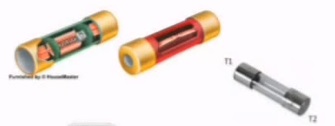
Cartridge Fuse

Cartridge Fuse

This fuse unit is in the form of a cartridge.

Its normally manufactured in the range of 2 A to 100 A.

Whenever the fuse blows off,fuse with carrier is replaced by a new one.

As it is sealed,it cannot be rewired.

Cartridge fuses are used to protect motors and branch circuit where higher amps or volt ratings are required. They are available in wide variety of sizes,amp and volt ratings up to 600 Vac and 600 amps.

Cartridge fuses are used extensively in commercial,industrial and agricultural applications as well as residential fuse panels,air conditioning,pumps,appliances and other equipment.

Cartridge Fuses are available in two types-

General purpose fuses have no time delay and protect fuse panel,appliances and branch circuits
Heavy duty fuses have a time delay feature.
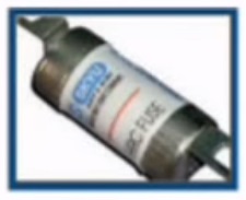
HRC Fuse

HRC Fuse


HRC Fuse – High Rupture Capacity fuse unit.It is normally designed for high current.When fuse is blown off,the entire unit is to be replaced by a new one.It cannot be rewired as it is a sealed one.

Characteristics of a good fuse wire

A good fuse wire should possess the following characteristics
a)Low resistivity
b)Low melting point
C)Low conductivity of the metal vapors formed,when the fuse is blown off.

Advantages of HRC Fuse

1.They require maintenance
2.They are reliable
3.They operate at high speed.
4.They have consistent performance
5.They clear both low and high fault current with equal efficiency.

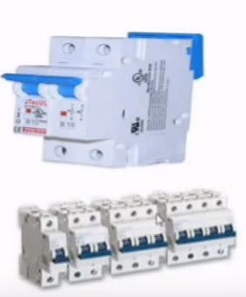
2.MINIATURE CIRCUIT BREAKER 

Miniature Circuit Breaker


It is safety device which work magneto thermic release principle.It is connected in the phase,between the supply and load.It is manufactured in standard rating of 6A to 40 A.We can see it on the meter board of each and every house.

When the current drawn by load exceeds the rated value,it acts and trips the circuit,the protecting the apparatus,operator and appliance.

Advantages of MCB

1.They act and open the circuit in less than 5 milli seconds.
2.Automatic switch off under overload and short circuit condition
3.No fuse to replace or rewire.It needs no repairs.
4.Supply is restored by resetting it again.

3.EARTH LEAKAGE CIRCUIT BREAKER

This is a domestic safety device,which trips the circuit when there is a small leakage to earth or body of the appliance.Thus it protects the operator from shocks and accidents.This is connected in the circuit of the appliance to be protected.

There are two types of ELCB
1. Voltage Earth Leakage Circuit Breaker
2. Current Earth Leakage Circuit Breaker

4.MCB & ELCB

It is the combination of both MCB and ELCB palced in one unit.It acts on both the occasion of   earth leakage and overload and protect the circuit,appliance and the operator.

5.EARTHING OR GROUNDING

Connecting the metal body of an electrical appliance,machinery or an electrical installation to earth,through a low resistance wire,is called Earthing or Grounding.

Necessity of Earthing 

Earthing is necessary for all domestic,commercial and industrial installation to safeguard the operator,tall buildings and machinery against lightning.

Metal body of all the electrical appliances,equipment and machinery,the earth points of all three-pin sockets and the body of the energy meter are connected to earth through a thick G.I. wire.

Whenever a live wire comes in contact with the body of the appliance,it is directly connected to earth the grounding wire and hence the body voltage comes to zero.Therefor the operator does not get any shock,when he comes in contact with body of the appliance.

The high voltage included during lightning  is discharged to earth through grounding wire and thereby building and machinery are protected.

Basics of PID controller (Proportional – Integral – Derivative)

0

PID (Proportional – Integral – Derivative ) Controller

How PID works - Animation


Proportional

The proportional term makes the current error signal multiplied with a gain (Kp).The result will be output signal.

So output signal = Kp * Error_Signal

Integral

The integral term makes the current error signal value and duration multiplied by with a gain (Ki).
The result will be the output signal.

So output signal = Integral term output signal

Where Ki – is the integral gain
t is the instantaneous time
e(t) – is the error signal

The integral of a signal is the sum of all the instantaneous values that the the signal has been,from whenever you started counting until you stop counting.

The integral term (when added to the proportional term) accelerates the movement of process towards setpoint and eliminates the residual steady-state error that occurs with a proportional only controller.

Derivative

The derivative term makes the rate of change the error signal multiplied with a gain (Kp).The result will be the output signal value.

So output signal  =  Derivative control equation

-where Kd is the derivative gain
-e(t) is the error signal .

The derivative term slows the rate of change of the controller output and this effect is most noticeable close to the controller setpoint.

PID Control System

Here is block diagram of a PID control system.
Includes the :
-PID Controller
-Process/Plant
-Feedback
-Setpoint

PID Control System
The setpoint is the value that we want the process to be.
The output must be equal to the setpoint,else error signal will not be zero.
The error signal will be the [Setpoint – Measured]
The 3 gains [P,I & D] will be summed together to output 1 signal that will get the output equal to the setpoint
The process is the plant plant/model of the system. Example – Motor
A disturbance is added to system. Example – Friction to shaft of the motor.
PID Controller Block Diagram
The setpoint is subtracted from the measured to create the error.
The error is simply multiplied by one,two or all of the calculated P,I and D actions.
Then the resulting “error x control action” are added together and sent to the controller output.


Override Control

0

Override

It is sometimes necessary to limit a variable in order to maintain safe operation or protect process equipment. If this variable is a function of the system’s primary controlled variable, the two variables can be interlocked in an override system. The primary variable maintains control as long as the second variable does not exceed its safe limit, at which point the second variable assumes control.
In the compressor control system shown below, discharge pressure is controlled by PC1 manipulating the bypass valve so long as suction pressure remains above its low limit. However,  when suction pressure reaches the limit value, PC2 takes over control and holds it until normal conditions are re-established. The take-over in either direction is through a low selector and is both bumbles and automatic. Both controllers are proportional plus reset and must have external feedback from the selector output (not shown in the figure) for smooth take over.
In this example, the suction controller is direct acting , the discharge controller is reverse acting and the valve is air-to-close. Other examples include reactor temperature control with pressure override and compressor discharge flow control with discharge pressure override.
Override Control

Feedforward Control System

0

Feedforward

A Feedforward control system measures a disturbance in variable, predicts its effect on the process and applies corrective action.

Given an exact model of the process, the feedforward controller will adjust the manipulated variable (m) so that the controlled variable (c) is unaffected by the disturbance. In fact, the controlled variable has no influence over the control, corrective action is totally in response to their disturbance u1.

Feedforward_Control_System

This system has three major drawbacks :
1.  The model must be exact (including dynamics and nonlinearities).
2.  All instruments in the loop must be perfectly calibrated.
3.  Disturbances other than the feedforward variable are not controlled.

Thus feedforward by itself is insufficient control. However, combined with conventional feedback, it can be a powerful control tool. If a load change in a process occurs so frequently that the controller cannot keep up, or if the disturbance is so large that the controlled variable cannot be held within tolerable limits, and if the disturbance variable cannot be controlled, consider adding feedforward control to the system.

The feedback controller does the same job and has the same responses and settings as if it were acting alone. It does not have much work to do. The feedforward control cancels the major effect of the measured disturbance. Since feedback acts as the system’s watchdog,  the process model need not be exact. In fact, simple gain and lead-lag element will usually suffice.

The effect of load changes other than the measured disturbance will be corrected by the feedback system.

Feedforward and Cascade are often confused because of their similarities : two measured variables, one manipulated variable, one independent set-point. But cascade systems control both measured variables, with the master determining the set-point of the slave. In contrast, feedforward and feedback corrections independently adjust the control valve and there is no control applied to the feedforward variable.

Cascade Control System

0


Cascade

In cascade control system two controllers are cascaded  to each other as shown in the diagram below.  Primary controllers output is fed to secondary controller as a Set point. Both the controllers has their own sensing elements but only secondary controller gives output to the control valve. Primary controller receives set point from operator
Cascade Control Loop
For example in Batch reactor temperature is controlled using Cascade control strategy. The output of temperature controller TC-1 adjusts the set point of TC-2 in the batch reactor control system. The primary variable batch temperature is controlled by the master controller, but not by directly adjusting the cooling water valve. Instead, it manipulates the set point of the slave or secondary controller, which in turn supplies jacket water at the asked for temperature. There are two controlled variables, one manipulated and one independent set point.
example of cascade control system
Cascade controller tuning –
1.First,tune the secondary controller (with the primary controller in manual mode)
2.Then,tune the primary controller (with the secondary controller in cascade mode)
Cascade control has two functions :
1. Reduce the effect on the total control system of the dynamic elements in the secondary loop.
2. Correct for  disturbances which occur within the secondary loop before they affect the master loop (such as cooling water temperature changes).
The slave controller need have only proportional response. The major time constant must not be in the slave loop.
Cascade control is normally not applied in fast control loops – flow, pressure, etc. It is more useful in temperature or composition control systems.

Ratio Control

0

Ratio Control

In Ratio Control, the controlled variable is the ratio of two measured variables. Control is effected by adjusting one of the variables –  the controlled variable, to follow in proportion to a second – the wild variable. The proportionality constant is the ratio.
Ratio relays are nothing more than manually adjustable gain devices and the ratio setting is the true set-point of the system. If the flow measurements are with differential pressure transmitters, the actual linear ratio setting must be the square of the required ratio. Most ratio relays have optionally calibrated scales which allow direct setting of the required ratio.
Ratio Control
Ratio Control often monitors processes that require mixing one material in proportion to another.
For example, the product may require one part of material A for every two parts of material B.
With ratio control one of the materials flows at the rate required by other parts of the process.This is known as the wild flow. The flow rate of the second,called the controlled flow could be adjusted by a ratio controller.
The ratio control loop uses the rate of the wild flow to determine the rate of controlled flow so that the materials are mixed in the appropriate ratio.
Ratio control loop has one sensor and transmitter in the wild flow and another set in the controlled flow.Both sensors transmit signals representing the respective flow rates to the ratio controller.
The controller maintains the flow rate of the the controlled flow at a ratio to the wild flow.
The desired ratio is set by adjusting ratio the setpoint. Ratio control then monitors the value of one variable and sets the value of the second variable at a specific ratio to the first.