PID (Proportional – Integral – Derivative ) Controller

Proportional
The proportional term makes the current error signal multiplied with a gain (Kp).The result will be output signal.
So output signal = Kp * Error_Signal
Integral
The integral term makes the current error signal value and duration multiplied by with a gain (Ki).
The result will be the output signal.
So output signal = 
Where Ki – is the integral gain
t is the instantaneous time
e(t) – is the error signal
The integral of a signal is the sum of all the instantaneous values that the the signal has been,from whenever you started counting until you stop counting.
The integral term (when added to the proportional term) accelerates the movement of process towards setpoint and eliminates the residual steady-state error that occurs with a proportional only controller.
Derivative
The derivative term makes the rate of change the error signal multiplied with a gain (Kp).The result will be the output signal value.
So output signal = 
-where Kd is the derivative gain
-e(t) is the error signal .
The derivative term slows the rate of change of the controller output and this effect is most noticeable close to the controller setpoint.
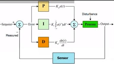
PID Control System
Here is block diagram of a PID control system.
Includes the :
-PID Controller
-Process/Plant
-Feedback
-Setpoint