- What are the types of electrical drawings?
- What is a one-line diagram?
- Why do we need single line diagram?
- What is a three-line diagram and how is it different from a single-line diagram?
- What is a wiring diagram and how to interpret it?
- What is a schematic diagram?
- What is the difference between the schematic diagram and the wiring diagram?
- What is a block diagram and how to interpret it?
- How to read the electrical diagram?
- How to interpret the ladder diagram (line diagram)?
- How to determine the wiring and wire identification in an electrical diagram?
- What is the purpose of using device abbreviations in an electrical diagram?
- What is the purpose of the line number and wire number in an electrical diagram?
Electrical drawings are single-line drawings that use certain symbols to represent the electrical equipment. Electrical diagrams are mostly multi-sheet drawings of the wiring of the electrical devices which is associated with the main control panel its field device and sub-panels. Mostly these drawings are drawn in a format called the ladder diagram. Another form of electrical drawing is a wiring diagram and it would show the wiring in a pictorial format.
What are the types of electrical drawings?
- One-line diagram (single line diagram)
- Wiring diagram
- Ladder diagram (line diagram)
- Block diagram
- Schematic diagram
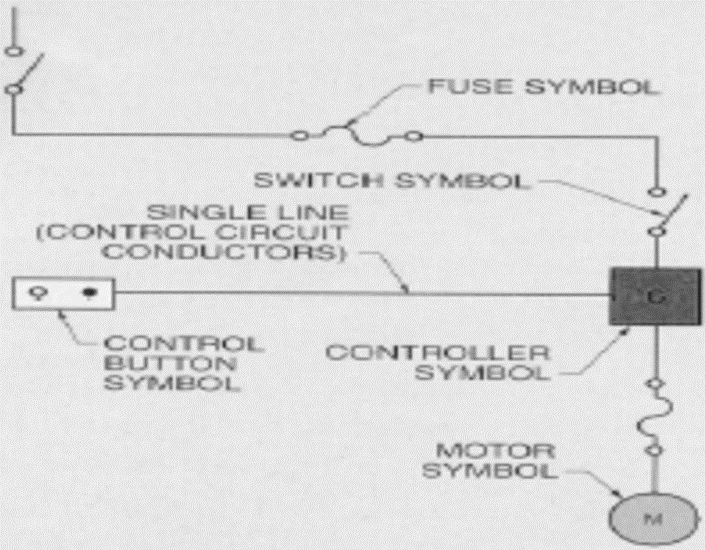
What is a one-line diagram?
This type of electrical diagram would use single lines and symbols to show the path and also the components in an electrical circuit. By using this diagram we could determine the circuit connection and their component, but we won’t be able to determine the actual location of the component by using this diagram. By using a line diagram, we could easily determine the connections and also the components in an electrical system. This diagram is widely used in an industrial power system, in this diagram multiple conductors of power and control circuits are shown as single lines.
Why do we need single line diagram?
- It can be used to create project drawings
- Power system problems can be analyzed
- We could determine which circuit interrupts must be opened to isolate the electrical circuit during faulty conditions
- We would be able to interpret the proposed installation of a power system
What is a three-line diagram and how is it different from a single-line diagram?

A three-line diagram would give us detailed information about the three-phase circuitry which can’t be seen in a single line diagram. The three-line diagrams would be more useful for the plant maintenance and the operator would be able to determine operations of a power system with the help of a three-line diagram. These diagrams are used to create the wiring diagrams of protective relays. The symbols which are used in this diagram would be the same as in the single line diagram, most of the electrical diagrams would use the same symbol to represent the electrical component.
What is a wiring diagram and how to interpret it?

The wiring or connection diagram is an electrical diagram that would show the connection of installation or its component device or parts. According to the wiring diagram the electrical inspector can do the electrical wiring in an industry. This diagram would be useful during the wiring and also after the completion of the wiring. The major benefit of a wiring diagram is that it would show almost the proper location of the component in a circuit. These diagrams are used by the equipment manufacturers to install the wires in electrical equipment such as switchboards and panels. We can also determine the interconnection of the electrical component by using this diagram. This diagram would display the electrical equipment in its proper physical location and thus it can be used to check the actual location of the equipment.
Single conductors are represented by lines. The multiple conductors which are bundled together or which are installed in the same channel will be shown with single lines with radial branches to show the location where the single conductors or other bundles leave the path of the main trunk bundle. Each conductor would have a unique number. So with the help of this diagram, we could determine the point-to-point wiring between the components in an electrical system. In a wiring diagram, the power circuits are denoted by the bold lines, and the control circuit is represented by the thinner lines. During certain cases, wiring diagrams are used in conjunction with the ladder diagram so that the control process can be easily determined.
What is a schematic diagram?

A schematic diagram would be mostly, prepared by the equipment manufacturer to show how to do the electrical connections. These diagrams would be very useful for the testing, maintenance, and also troubleshooting of the equipment. The ladder diagram is a type of schematic diagram. This diagram would display the circuit elements and also the internal connections and this would be very useful for the electrician to interpret the function and also the logic of an electrical control circuit. These diagrams are prepared to design electrical circuits. The schematic diagram uses the same symbols as in the one-line, three-line, and wiring diagrams. This diagram would display all the connections and terminals of a functional device. We can describe this electrical diagram as the operational sequencing of the circuit.
What is the difference between the schematic diagram and the wiring diagram?
| Sl no | Wiring diagram | Schematic diagram |
| 1 | It shows the connection between circuit elements or system | It shows the flow of a system |
| 2 | Wires are represented by horizontal and vertical lines | System flow is represented by horizontal and vertical lines |
| 3 | Simple pictorials are used which represents the components in a circuit | It uses symbols that represents the circuit functions |
| 4 | The equipment and wiring in this diagram is displayed as in the actual location of the system | It doesn’t show the physical layout of the system in this drawing, it would show the flow of the system |
What is a block diagram and how to interpret it?

The block diagram is the easiest way to determine the electrical system. These diagrams are used to represent the complex systems to show the flow path of the signal. A block diagram shows the major functional parts of a complex electrical system by blocks instead of symbols. In this diagram, we won’t be able to see the individual components and wires. Each block in this diagram represents the electrical circuit that performs specific functions in the system, the function of the circuit will be written in each block.
How to read the electrical diagram?
In order to read any of the electrical diagrams, we must be familiar with the graphical symbols which is used to represent the electrical components. In most of the electrical diagrams, the symbols which is used to represent the electrical component would be the same. So it is really important that one should have an idea about the graphical symbols to read the electrical diagram.
Graphical symbols in the electrical diagram
Graphical symbols are required in an electrical diagram to show the electrical device connections and their terminals. The electrical devices would be represented by symbols. The symbol orientation in an electrical diagram won’t change its meaning or purpose.
Graphical symbols in electrical diagram
| Sl no | Electrical equipment | Graphical representation of the electrical device |
| 1 | Circuit breaker |  |
| 2 | Resistor | |
| 3 | Potentiometer |  |
| 4 | Fuses | |
| 5 | Relays | |
| 6 | Coil |  |
| 7 | 3-phase motor |  |
| 8 | Capacitors |  |
| 9 | Inductors |  |
| 10 | Voltage sources |  |
| 11 | Batteries |  |
| 12 | Diodes |  |
| 13 | Switches |  |
| 14 | Logic gates |  |
| 15 | Voltage nodes | |
| 16 | Transistors |  |
| 17 | Transformer |  |
| 18 | Amplifier |  |
| 19 | Digital to analog converter |  |
| 20 | Analog to digital converter |  |
How to interpret the ladder diagram (line diagram)?

The above electrical diagram is drawn in a ladder diagram and it will be drawn by adding the circuit between the two vertical lines as we can see in the above image. The ladder diagram is also called the line diagram and it would show the electrical system logic by using symbols.
These vertical lines would provide the power, all the devices would be shown between these lines and it is called a single line diagram. So the controlled devices such as relays will be drawn on the right side as we can see in the image and the controlling device would be placed between the controlling device and also the left vertical line. The circuit-breaking devices and the overloads will be placed or connected to the right of the controlled device.
Determine the line connection in the diagram
Wiring

Field wiring (wiring which is external to panel)

Wiring connections in the electrical diagram
Connected wiring

Wiring which is not connected

How to determine the wiring and wire identification in an electrical diagram?
Wiring color code
- RED –AC control circuits
- Black – Line, load, and control circuits
- Blue – DC control circuits
- Yellow – Interlock control circuits
- Green – Equipment grounding
- White – Grounded circuit conductor
Wire identification
We can determine the conductors in each termination by marking with a number corresponding with the number on the wire.
What is the purpose of using device abbreviations in an electrical diagram?
The device’s abbreviations are used in the electrical diagrams in connection with the corresponding graphical symbols so that the function of the particular device can be indicated.
- CB – circuit breaker
- CR – Control relay
- FU – Fuse
- LT – Pilot light
- OL – Overload relay
- PB – Push button
- S – Switch
- LS – Limit switch
- T – Transformer
- MTR – Motor
- Disc – Disconnect
- R – Resistor
- C- Capacitors
- L – inductors
- S – switches
- D – Diodes
- Q – Transistors
- U – Integrated circuits
- Y – Oscillators
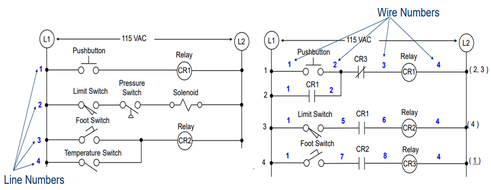
What is the purpose of the line number and wire number in an electrical diagram?
Each line in the electrical diagram will be numbered from top to bottom, and also there will be wire numbers in the electrical diagram to determine the wire and its connection. So in case of any fault, we could determine the faulty section by using the line and wire number. Control devices are represented in the electrical diagram by abbreviations and also by numbers and this would be the number of the line where the device is located. So with the help of line and wire numbers, we can easily detect where the devices are located in an electrical system.