- What are the symbols used in single line diagram?
- Various components involved in a single line diagram
- Why single line diagram?
- What is the purpose of a single-line diagram?
- What are the pieces of information that we could get from a single-line diagram?
- How to create a single-line diagram?
- What are all the details that must be in a single-line diagram?
- What are the advantages of a single-line diagram?
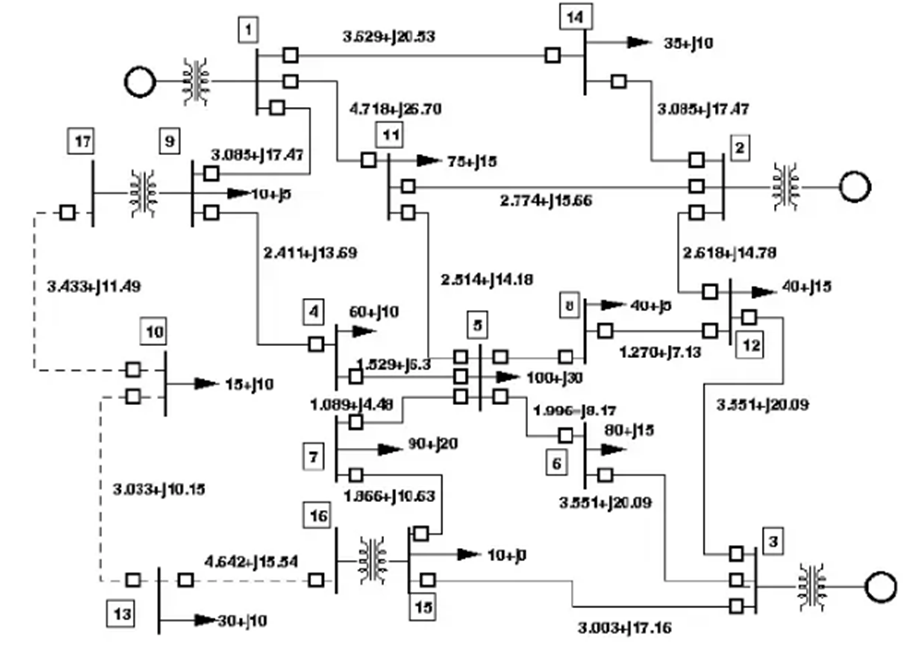
A single-line diagram would use graphical symbols and single lines to indicate the components and path of an electrical circuit. We won’t be able to determine all the electrical connections with the help of a conventional diagram and in this situation, a single line diagram would be useful. This diagram would easily describe a three-phase system.
The single-line diagram is also called a one-line diagram. These diagrams would be useful to get details about the circuit but they won’t be able to show the actual wire connection and operation of the circuit. So basically, this diagram does the symbolic representation of the electrical system which is in a circuit. With the help of a single line diagram we can easily determine the circuit interconnections and also we could easily find the physical location of a circuit or component. This type of diagram is mostly used in an electrical power system. All the connections are shown as single lines, the multiple conductors of power circuits, and the control circuits are shown as single lines.
What are the symbols used in single line diagram?
| SL no | Electrical components | Symbols |
| 1 | AC generator |  |
| 2 | Bus bar |  |
| 3 | Power transformer – two winding |  |
| 4 | Three winding transformer |  |
| 5 | Current transformer | |
| 6 | Voltage transformer |  |
| 7 | Circuit breaker |  |
| 8 | A circuit breaker with an isolator |  |
| 9 | Isolator |  |
| 10 | Lightning arrestor |  |
| 11 | Earth switch |  |
| 12 | A wave or line trap |  |
| 13 | Machine or a rotating armature |  |
| 14 | Three winding power transformer |  |
| 15 | Fuse | |
| 16 | Three-phase three-wire delta connection | |
| 17 | Three-phase wye neutral underground | |
| 18 | Ammeter and voltmeter | |
| 19 | Normally open contact | |
| 20 | Normally closed contact |  |
| 21 | Control switch |  |
| 22 | Push-button |
Various components involved in a single line diagram
Generator
The generator would act as a power source
Bus bar
The bus bar is used in a plant to reduce the energy loss in transmission and distribution. Bus bar can be seen in panel board, switch-gear, etc.
Power transformer
These transformers are used for generation and transmission purpose and it is used to step up the voltage.
Current transformer
These transformers are used to supply power to the instruments, these instruments are designed to operate in low-value current.
Potential transformer
These transformers are utilized to make the low voltage instrument suitable for the measurement of high voltages.
Circuit breaker
This is utilized to open or close a circuit, so this device would be really useful during faulty conditions.
Isolators
These devices are utilized to isolate a part of the system and they can be utilized during maintenance
Lightning arrestors
This device is used for protecting the instruments from lightning strokes. These devices would be located in tall structures and in substations they will be located in the starting point.
Earth switch
This is a switch which is used to discharge the electric charge to the ground
Wave trap
It is used in a substation to trap the high-frequency communication signals which are sent on the line from the remote substation and to divert them to the telecom panel
Coupling capacitors
This device is used in substations where the communication is done through AC power lines. It would provide very low impedance for the high-frequency carrier signal and it would allow them to enter into the line matching unit and it would block the low-frequency signal.
Why single line diagram?
A power system can be described as a complicated electrical network, especially an industrial electrical network. In a three-phase electrical network, all the components would be connected in three-phase and there will be three conductors for each power circuit. So a conventional diagram would display all the connections and this will be really hard to determine the entire plant layout and due to this, a single line diagram is utilized.
- It can be used for short circuit calculation
- Load flow can be determined
- Ensure the safety of the plant
- Proper maintenance can be done
- We can reduce the maintenance cost with the help of an accurate single line diagram
What is the purpose of a single-line diagram?
- We can easily analyze the power system problems
- Determine which circuit interrupters must be opened to isolate the electrical apparatus
- We can check this diagram to produce project drawings
- This diagram would show the power path of the electrical circuits or a system of circuits
- It would also show the devices or parts of a power system
- With the help of this diagram, we could easily determine the power flow in an electrical system that has different voltage levels
- We can easily determine the overall electrical power distribution in a plant
- The safety of the plant can be improved
- If the single line diagram is properly done then the operator safety can be ensured
What are the pieces of information that we could get from a single-line diagram?
- Generation and power evacuation voltages
- Auxiliary power supply voltages
- We could determine the power evacuation arrangement like the bus configuration
- Interconnection of electrical components
- We could get the specification of the individual equipment such as power and distribution transformers, MV and LV switch gears, etc.
- It would show the entire power distribution arrangement from the power receiving and evacuation of the EHV level to the load distribution at LT level up to the main switch gears.
- Incoming power line
- Protective devices
- We could also get the details of emergency equipment such as UPS, batteries, generator, power distributor, etc.
How to create a single-line diagram?
A single line diagram must be created by short straight lines and with components like a block diagram. The diagram should be drawn in a way that we should be able to get the whole picture of the electrical system. If the system which is drawn is really big and more than one sheet would be required to do this so in that case, a break should be made at voltage levels or at distribution centers.
Proper geographic relations must be kept
In certain cases, the single line diagram would be superimposed onto the industrial plot plan and during this case, it will be really useful to determine the location of the component in the plant. But during this case, it would be really difficult to determine the overall system operation. So in order to determine the complex systems, it must be used in addition to the fundamental single line diagram.
Keep the component position properly
While drawing this diagram it must be kept simple as possible and the component position must be placed in the diagram as the operator would view this equipment in the industrial plant. In order to properly do this a site plan with equipment location is needed.
There shouldn’t be any duplication
In this diagram, each symbol, figure, and letters have a unique meaning. So before creating this diagram, the equipment names must be chosen before the submission of this diagram, then these names can be used again according to the plant layout.
What are all the details that must be in a single-line diagram?
- The voltage of the incoming lines
- Main fuses and switches
- Power transformers
- Feeder breakers, relays, and fused switches (with rating and their type)
- Current and power transformer ( ratio, size, type)
- Control transformer
- It must have all the major cables and wire runs
- Details of the emergency equipment such as UPS, generator, etc
- Load schedule for the LT and distribution panels
- Bus bar details
- Outgoing cable details
- Earthing cable details
- Connected loads ( load capacity)
- Details of the earthing system must be included
What are the advantages of a single-line diagram?
- We can easily find out the faulty circuit or component
- Easy troubleshooting
- It would be useful for future testing
- We could do the service and maintenance easily
- It would show how the major components of an electrical system are connected
- The power distribution path can be determined
- We could get the specification of the electrical appliances