
- Types of RTD Calibration Methods
- Step 1: Prepare the tools required for RTD calibration
- Step 2: Safety Precautions
- Step 3 : Prepare the calibration setup for RTD
- Step 4 : Calibration of RTD
- Step 5: Enhance RTD Calibration with Calculators
- Step 6: Recording Calibration and Verifying Linearity
- Step 7: Completion of Calibration
- Step 8: Calibration Report Preparation
- How to Calculate RTD Calibration Error
- Recommended Calibration Intervals for RTD
- Recommended Products for RTD Calibration
- Standards Applicable to RTD Calibration
- Frequently Asked Questions About RTD Calibration
An RTD calibration procedure verifies whether a Resistance Temperature Detector measures temperature within its specified accuracy. Industrial instrumentation engineers use RTD calibration to maintain reliable temperature measurements in process plants, refineries, petrochemical facilities, power plants, and manufacturing systems.
RTD calibration can involve comparing the actual sensor against a calibrated temperature reference or simulating its resistance to check the connected temperature transmitter. The correct method depends on whether the objective is to verify the sensor, transmitter, or complete temperature measurement loop.
This guide explains the eight steps of RTD calibration, the equipment required, Pt100 resistance calculations, calibration test points, acceptance criteria, common errors, and calibration report preparation.
What is RTD?
RTD stands for Resistance Temperature Detector, a sensor measuring temperature by changes in electrical resistance. Commonly used in industrial applications, it provides accurate and stable temperature readings for various processes.
This below Step by Step calibration procedure provides a thorough explanation of how to calibrate a RTD using reference standards.
Types of RTD Calibration Methods
| Method | What is tested | Typical equipment |
| Actual sensor calibration | Sensor response against a known temperature | Dry block calibrator or temperature bath and reference thermometer |
| RTD transmitter simulation | Transmitter response to simulated RTD resistance | Multifunction process calibrator or resistance simulator |
| Complete loop verification | Sensor wiring, transmitter, signal transmission, and control system indication | Suitable temperature source, process calibrator, and DCS or PLC display |
Actual sensor calibration verifies the sensing element against a reference temperature. Resistance simulation checks the transmitter without necessarily testing the physical sensing element. A complete loop check verifies the measurement path, but does not replace a traceable calibration of the sensor when one is required.
Step 1: Prepare the tools required for RTD calibration

- Necessary hand tools.
- Multifunction process calibrator.
- Standard Multimeter.
- Test leads and probes.
- Soft Cloth for cleaning.
- Dry Bath temperature calibrator.
- Standard Reference Thermocouple
- Digital Standard Thermometer
Step 2: Safety Precautions
- For more information on general calibration process recommendations and basic safety in the process business, please click this page.
- Process Industry Calibration Methodology: Essential Safety and General Considerations
- Request that the panel operator set the controller’s MOS (Maintenance Override Switch) in manual mode for the RTD control loop and the ESD loop.
- It is necessary to locate the RTD that requires calibration.
- Verify that the RTD is the correct one and record any important details, like the tag number (e.g. the manufacturer, model number, temperature range, type of sensor, coefficient factor & etc.).
- Remember that this fundamental approach may need to be modified based on the specific RTD and the process location. Always follow local safety regulations and the manufacturer’s instructions when working with an RTD or any other component of process equipment.
- Follow all relevant lockout/tagout instructions to prevent an inadvertent start. Make that the RTD and its signal are separated from the operation.
- Prioritizing safety is crucial when calibrating an RTD. This includes using the proper PPE, removing and inserting the RTD from dry block, and isolating the process area.
- Always adhere to local safety regulations and guidelines, and make sure that all personnel involved in the calibration process are aware of and comply with the specified safety measures.
- Regular safety training and awareness can significantly contribute to a safer work environment during RTD calibration.
Step 3 : Prepare the calibration setup for RTD

- Ensure that the location chosen for RTD calibration, as well as the positioning of calibration tools, is completely without of electromagnetic interference and vibrations. Additionally, ensure the calibration area is well-lit and adequately ventilated.
- Collect all the necessary tools and supplies essential for the RTD calibration.
- Refer to the instrument loop diagram to power off the temperature transmitter connected to the RTD undergoing calibration. Remove any wires or connectors from the nearby junction box or Marshalling panel accordingly.
- Identify the RTD cable linked to the temperature transmitter, usually marked with a core. This cable might be connected to a separate terminal block or connector on the RTD temperature transmitter.
- Inspect the removed RTD cable for signs of wear or damage before re-attaching it to the temperature transmitter; replace it if necessary. Label, insulate, and secure the removed cable for later reconnection post-calibration.
- Carefully extract the RTD from the process equipment and place it in the calibration area. Once the RTD temperature normalizes to room temperature, clean the sensing surface to remove any dust.
- Get the temperature calibrator and a suitable thermowell, considering the RTD size and process temperature range. Refer to the instrument data sheet for the measuring range.
- Ensure that all relevant documentation, including the manufacturer’s manuals for the RTD and calibration tools, is available and up-to-date.
- Prior to use, check the calibration status and validity of the multifunction process calibrator, standard multimeter, and other calibration tools.
- Take note of the area’s surrounding temperature and humidity levels as these can have an impact on the accuracy of the calibration.
- Place the RTD in the dry block calibrator with the appropriate thermowell. Obtain a suitable standard thermocouple with a thermometer insert along side the RTD in the thermowell of the calibrator to compare the temperature in the dry block calibrator.
- Ensure that the RTD is immersed to the correct depth in the dry bath calibrator, considering the immersion depth specified in the instrument data sheet.
- Use a multifunction process calibrator and connect the RTD terminals to measure the output resistance in terms of temperature. For a 4-wire RTD, connect all four wires to the multifunction calibrator using probes and leads, following the diagram provided.
- Upon completing the connections as illustrated in the diagram, the setup is now ready for the calibration of the RTD.
How do you calibrate a RTD sensor?
Step 4 : Calibration of RTD
- Check the connections and ensure that there are no loose wires or poor connections.
- Power on the dry block calibrator and set it to the desired temperature for calibration. Consider the type of RTD for calibration, adjusting the dry bath calibrator’s set temperature accordingly, incorporating any range locks.
- Take precautions not to exceed the temperature range of the RTD; consult the data sheet and nameplate for capacity information. Adjust the dry bath calibrator’s temperature as needed based on this information.
- Allow sufficient time, typically several minutes, for both the RTD and dry bath calibrator to stabilize at the same temperature.
- Monitor the multi-function calibrator for the RTD’s measuring temperature indication, observe the dry bath calibrator’s reading, and note the reference thermometer’s indication at the reference temperature.
- Confirm the stability of the dry bath calibrator and the multifunction process calibrator readings before starting the calibration procedure.
- Record both temperature readings from the calibrator and corresponding resistance values from the RTD using the multi-process calibrator.
- Configure the multi-function calibrator to measure temperature instead of resistance by referencing the RTD’s nameplate for the proper coefficient factor.
- Repeat the calibration process for each calibration point, ensuring enough time for stabilization before recording measurements. If temperature adjustments are made during the process, re-stabilize the system before recording final readings.
- Repeat the procedure for various reference temperatures, spanning the entire range from 0% to 100% on the RTD’s scale, to comprehensively calibrate it.
- Calculate the expected resistance from the RTD concerning the known temperature, utilizing the RTD coefficient factor (e.g. 0.00392, 0.00385) and the RTD type (e.g., PT100, PT500).
- Check for any calibration adjustments in the RTD; typically, RTDs do not require correction. Refer to the manufacturer’s provided accuracy specifications and ensure that the results are within tolerance. If not, consider for replacing the RTD.
- Before initiating the calibration procedure, carefully review the manufacturer’s instructions, as the process may vary depending on the specific dry block calibrator used.
Step 5: Enhance RTD Calibration with Calculators
RTD Resistance Calculation Formula
For a limited temperature range above 0°C, a simplified approximation is:
RT=R0(1+T)
Where:
- RT is the approximate resistance at temperature T.
- R0 is the resistance at 0°C.
- is the nominal temperature coefficient.
- T is the temperature in degrees Celsius.
For a standard Pt100 with R0=100 and a nominal coefficient of 0.00385, the simplified formula gives:
R30=100(1+0.0038530)
R30=111.55
This is an approximation, not the exact IEC 60751 resistance value. For accurate calibration across a wider range, use the applicable standard resistance table or Callendar Van Dusen equation with the correct coefficients. Do not use the simplified formula as the sole acceptance reference.
Pt100 Resistance and Temperature Reference Table
Values below are approximate for a standard platinum Pt100 with a nominal coefficient of 0.00385.
| Temperature | Approximate resistance |
| 0°C | 100.00 Ω |
| 25°C | 109.63 Ω |
| 50°C | 119.40 Ω |
| 75°C | 129.10 Ω |
| 100°C | 138.50 Ω |
Use the exact resistance table or equation required by the sensor specification when evaluating calibration errors. These approximate values are for quick reference, not a substitute for the applicable calibration standard.
RTD Temperature Transmitter Calibration Test Points
| Test point | Simulated temperature | Expected output |
| 0% | 0°C | 4.00 mA |
| 25% | 25°C | 8.00 mA |
| 50% | 50°C | 12.00 mA |
| 75% | 75°C | 16.00 mA |
| 100% | 100°C | 20.00 mA |
Use the transmitter’s configured sensor type and resistance curve to generate the input. The expected output follows the linear transmitter scaling:
I=4+16T-LRVURV-LRV
Where I is the expected current in mA, T is the simulated temperature, and LRV and URV are the configured lower and upper range values.
Important: This table checks the transmitter’s configured 4 to 20 mA output. It does not by itself prove the accuracy of the physical RTD sensor. Assess each device against its own applicable tolerance.
- Click here for RTD Temperature Coefficient Calculation to learn about RTD temperature coefficients and their impact on resistance variations.
- Click here for RTD Calculator: Converting Measured Resistance to Process Temperature to utilize this calculator to convert RTD measured resistance to accurate process temperature readings.
- Click here for RTD Calculator: Converting Process Temperature to measured Output Resistance to access this calculator to convert process temperature values into corresponding RTD measured output resistance for precise temperature measurements.
Step 6: Recording Calibration and Verifying Linearity
- Include inputs in both the upscale and downscale temperature directions from the dry block calibrators, corresponding to the output values indicated on the RTD in the multifunction calibrator.
- Recalibration is necessary if the RTD output value falls outside the tolerance specified by the manufacturer. In case of further deviation from the permitted range, replace the RTD with a new one.
- If every output value (+/- %) of the RTD is within accepted limits, no additional calibration is required.
- Fill in the “as found/as left” column of the blank calibration report with the RTD output values.
Step 7: Completion of Calibration
- After a successful calibration, affix the calibration label to the RTD.
- Clean the apparatus, store it securely, and record the calibration data for future reference.
- Remove the calibrators from their connections.
- Reinstall the RTD in the processing area.
- Ensure the workplace is tidy.
- De-isolate the equipment.
- After reinstalling the RTD in the processing area, perform a functional check to ensure that the RTD is operating correctly within the control loop.
Step 8: Calibration Report Preparation
The calibration of the RTD is demonstrated in the sample report using a thermometer and a dry bath temperature calibrator, with a standard thermocouple serving as the reference.
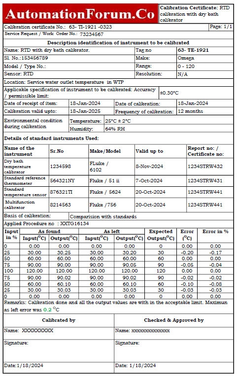
For an Excel template used in creating the RTD calibration report, you can access it through the link provided.
How to Calculate RTD Calibration Error
Error=Measuredvalue-Referencevalue
For example, if the reference thermometer reads 50.0°C and the RTD indicates 50.4°C, the error is +0.4°C.
The result is acceptable only if the error falls within the applicable tolerance. The acceptance limit depends on the sensor class, temperature range, reference equipment uncertainty, project requirements, and site calibration procedure. Do not apply a single tolerance to every RTD.
| Observed problem | Possible cause | Recommended check |
| Resistance is too high | Lead resistance or poor termination | Inspect wiring and connection resistance |
| Resistance is too low | Short circuit or incorrect wiring | Check terminal connections and insulation |
| Reading fluctuates | Loose connection, electrical noise, or unstable bath | Inspect wiring and wait for thermal stability |
| Three wire reading is inaccurate | Unequal lead resistance or incorrect compensation | Verify wiring and transmitter configuration |
| Four wire reading differs from expected | Incorrect connections or instrument setup | Verify the four wire measurement connections |
| Transmitter output is incorrect | Incorrect sensor type, range, or configuration | Verify RTD type, coefficient, LRV, and URV |
Insulation resistance testing must follow the RTD manufacturer’s instructions and the approved test procedure. Do not apply an insulation tester to a connected transmitter or other electronics.
Recommended Calibration Intervals for RTD
Regular calibration of RTD sensors ensures accuracy and reliability in temperature measurements. The calibration interval can vary based on the specific application, environmental conditions, and manufacturer recommendations. Generally, the following intervals are suggested:
- Industrial Applications: Annually or biannually, depending on the criticality of the process.
- Laboratory and Research: Every 6 months to 1 year for high-precision requirements.
- Harsh Environments (e.g., high vibration, extreme temperatures): Every 3 to 6 months.
- Critical Processes (e.g., pharmaceutical, aerospace): Every 3 to 6 months or more frequently, based on quality assurance protocols.
- General Maintenance: At least annually, with checks during major maintenance shutdowns.
Consult the RTD manufacturer’s guidelines and industry standards for more specific recommendations.
Recommended Products for RTD Calibration
To perform accurate and reliable RTD calibration, the following products are recommended:
Multifunction Process Calibrator
- Fluke 754 Documenting Process Calibrator: A versatile tool for calibrating, maintaining, and troubleshooting RTD sensors.
- Yokogawa CA500 Multifunction Calibrator: Offers high accuracy and supports various sensor types.
Dry Bath Temperature Calibrator
- Fluke 9142 Field Metrology Well: Provides stable and uniform temperatures for precise calibration.
- WIKA CTD9100: Known for its accuracy and stability, ideal for field and laboratory calibration.
Standard Multimeter
- Fluke 87V Industrial Multimeter: Reliable and accurate for various electrical measurements.
- Keysight U1282A: High precision and rugged design for industrial environments.
Standard Reference Thermocouple
- Omega Engineering Thermocouples: High-quality thermocouples for accurate reference temperature measurements.
- JUMO Thermocouples: Trusted for their precision and reliability in industrial applications.
Digital Standard Thermometer
- Fluke 1523 Reference Thermometer: Provides high accuracy for comparison during calibration.
- Omega HH41: Digital thermometer known for its precision and ease of use.
Calibration Software and Calculators
- Fluke Calibration Software: For documenting and managing calibration data.
- RTD Temperature Coefficient Calculator: Available online for accurate conversions of resistance to temperature and vice versa.
By following the recommended calibration intervals and using high-quality calibration tools, you can ensure the accuracy and reliability of RTD sensors in your industrial processes. Always adhere to the manufacturer’s guidelines and industry standards for optimal results.
Standards Applicable to RTD Calibration
- IEC 60751: Relevant to industrial platinum resistance thermometers and sensors, including resistance versus temperature characteristics and tolerance classes.
- ISO/IEC 17025: Specifies competence requirements for testing and calibration laboratories.
- IEC 61508: Relevant when the temperature measurement forms part of a functional safety system. It is not a general RTD calibration procedure standard.
- NIST traceability: Reference standards and measurement results may be traceable to national measurement standards through a documented calibration chain. Traceability alone does not establish that an instrument meets its required tolerance.
Frequently Asked Questions About RTD Calibration
What is RTD calibration?
RTD calibration compares the sensor or transmitter reading against a known reference. It verifies whether the measurement is within the specified accuracy.
How do you calibrate a Pt100 RTD?
Use a calibrated temperature bath or dry block and a reference thermometer to test the actual sensor. A resistance simulator can be used separately to verify the transmitter response.
What is the resistance of a Pt100 at 0°C?
A standard Pt100 has a nominal resistance of 100 ohms at 0°C. The resistance increases as temperature rises.
How many points are required for RTD calibration?
The number of test points depends on the approved procedure and required accuracy. Five points across the operating range are commonly used for transmitter verification.
What is the difference between RTD and RTD transmitter calibration?
RTD calibration checks the sensing element against a temperature reference. Transmitter calibration checks the conversion of simulated RTD resistance into the configured output signal.
Can an RTD be calibrated without removing it from the process?
Some in situ checks are possible using a suitable reference or comparison method. However, they may not provide the same level of verification as controlled sensor calibration.
What should an RTD calibration report contain?
Include the instrument tag, sensor type, range, reference equipment, test points, as found and as left readings, calculated error, acceptance limits, calibration result, and corrective action.
Why does a three wire RTD give an incorrect reading?
Unequal lead resistance, incorrect terminal connections, damaged wiring, or incorrect transmitter configuration can cause errors. Check the wiring and compensation method before replacing the sensor.
Click here for more Calibration Procedure
