The table below provides detailed guidelines for doing thorough troubleshooting of the conductivity transmitter.
What are the possible errors in conductivity measurement?
Display differs from the reference measurement
Possible cause
Solutions
Issues with the calibration
Conductivity transmitter needs to be calibrated using the instrument data sheet
Contaminated sensor
Clean the sensor
Inaccurate temperature measurement
Verify the conductivity cell’s and the reference unit’s(thermometer) temperature values
Improper temperature compensation
Verify both the method of compensation and the type of compensation
Incorrect calibration of the reference instrument
Use a calibrated instrument or calibrate the reference instrument
The conductivity sensor has a polarization error
Select a sensor with a higher cell constant.Instead of stainless steel, use an appropriate graphite sensor (check resistance)
Troubleshooting Conductivity Analyzer Common Problems
Measured values that are unreasonable:
This include continuous measured value overflow, measured values that are always zero, measured values that are too low or high, wrong current(mA) output value or a frozen measurement value
Cable used for cell temperature measuring is defective.
Check to see whether there is an interruption, short circuit, or shunt in the cable
Type of temperature sensor that is incorrect
On the instrument, choose the type of temperature sensor.
An inaccurate conductivity measured value was obtained during the process.
Possible cause
Solutions
There is no or insufficient temperature compensation
Automatic temperature compensation (ATC) chooses the type of compensation; linear or sets the correct temperature coefficient. Process temperature was set by Manual temperature compensation(MTC)
Incorrectly measuring the temperature
Utilize a thermometer or reference instrument to verify the temperature value of the sample.
Bubbles in medium
Use a gas bubble trap, counter pressure (cover) to prevent the development of bubbles.
Effects of polarization (on conductive sensors only)
1.Use the appropriate sensor and a larger cell constant.2. Refer the measuring range table in the technical data of the conductivity sensor.3. Replace stainless steel with graphite sensor (and test the resistance).
High flow rate could result in bubbles.
Flow should be reduced, or mount in a low-turbulence area.
Interference current in the medium (only when conductive)
The ground medium in close proximity to the sensor. The most common reason for currents in the medium caused by faulty submerged motors.
Contaminated or coated sensors
Sensor should be cleaned (refer the Cleaning of Conductivity Sensors in preventive maintenance of conductivity transmitter article ). Use spray cleaning for media that are really dirty.
Incorrect field line resistance
Enter the appropriate value.
Inadequate sample flow rate
Keep the sample flow in the right range as instructed by the instrument’s datasheet.
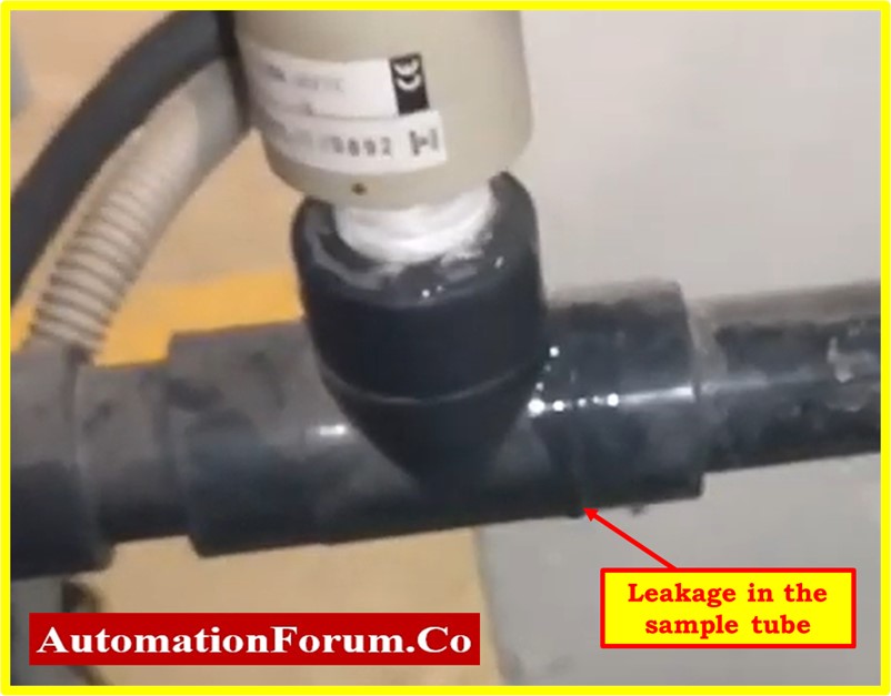
Sample tubes have a leak
Verify each tube connection. On the fitting side, there shouldn’t be any leaks. Additionally, no tube should be ruptured. If a leak has been identified, fix it.
The inside of sampling tubes can be chocked.
Use the pressure pump to de-choke the tube or flush the system. Use pressurized fluid that is no more than 1.5 times as pressurized as the process fluid.
Adjustment of the air calibration out
Verify the conductivity probe’s performance during the air calibration. The conductivity analyzer ought to display a reading of 0 for the atmosphere.
There is a problem with the transmitter calibration.
According to the connection diagram, connect the cable screen.
Interference in the signal output line
Ensure that the line routing is correct.Consider using separate line routing.Signal output and measurement input lines should be routed separately.
Interference currents in the medium
Getting rid of any interference sources or nearby ground mediums
Incorrect setup of the damping value
If the variations are extremely large, increase the dampening factor value of the conductivity analyzer.
The rate of sample flow is not constant.
Follow the vendor manual’s sample flow to the conductivity analyzer. The sample flow shouldn’t have air bubbles either.
There are leaks in the sample tube.
The conductivity reading will fluctuate as a result of minor tube leaking. So arrest the leak.
No current output signal for conductivity
Possible cause
Solutions
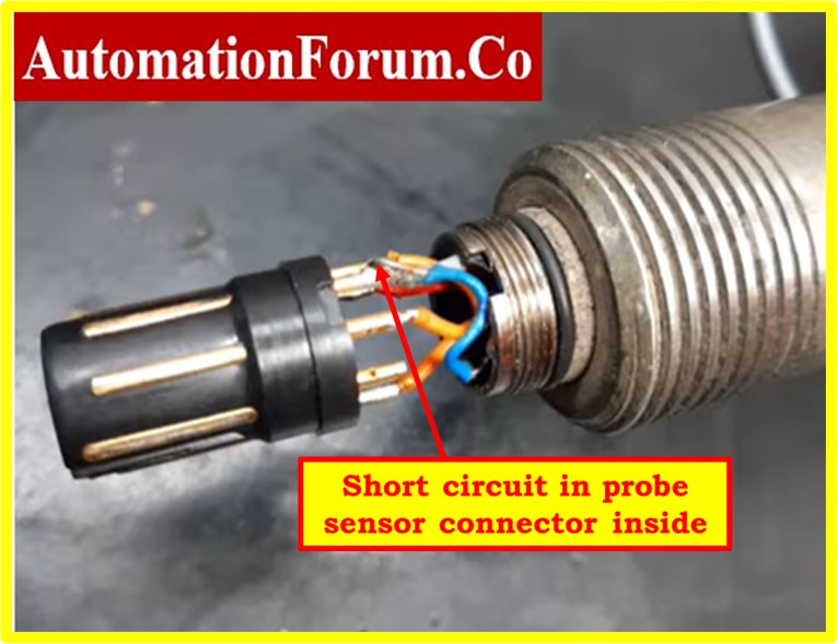
Open or short-circuited line
Disconnect the wire and use a multimeter to measure the instrument directly (4 to 20 mA).
Defective Current(mA) Output Module
It is recommended that you either repair or replace the module.
Current conductivity output signal with a fixed conductivity.
Possible cause
Solutions
Active simulation at the moment
Turn off the simulation.
processing system functioning in an inappropriate ways
Shut down and restart the instrument. If the issue persists, check the installation, screen, and grounding.
Current(mA) output signal that is incorrect
Possible cause
Solutions
mA Current assignment is incorrect.
Check the current assignment; it can be 0-20 mA or 4-20 mA.
Excessive total load in the current loop (>500).
Disconnect the output and use a multimeter to measure the mA directly on the instrument.
Issue with electromagnetic compatibility (EMC)
Directly measure on the instrument after disconnecting both output lines. Use shielded lines, ground screens on both sides, and if necessary, route the line via another duct.
No or a dark display
Possible cause
Solutions
Insufficient line voltage
Use a multimeter to check the supply voltage; it should be within the manufacturer’s suggested range.
Incorrect or too low supply voltage
Compare the name plate data and the actual line voltage.
Improper connection
Not properly tightened at the terminal.Insulation was stuck.Utilized incorrect terminals.
Faulty device fuse
Replace the fuse by comparing the nameplate information with the line voltage.
Faulty power supply card or unit
Replace the unit or the power supply card
Mismatch between field and PLC/DCS conductivity values
Possible cause
Solutions
Inaccurate field and PLC/DCS range configuration
Verify both sides of the range. and make sure they are identical to the instrument data sheet.
There is a force present in either the field conductivity transmitter or the PLC/DCS.
Remove force after carrying out the correct process for restoring force.


