Circuit diagrams virtually represent electrical symbols or electronic circuitry. The parts of a circuit are represented by a few common symbols. Some of the symbols that are widely used for designing circuits. To represent fundamental electrical or electronic devices, a variety of electrical and electronic schematic symbols are employed. Typically, apply these to build circuit diagrams.
- Earth electrode,
- Cell,
- Battery,
- Source,
- Ideal source,
- resister, etc.
are all represented by basic electrical symbols. These icons help in the development of detailed diagrams and documentation. Despite their complexity, electric circuits can be explained in a variety of ways. While an electrical circuit can be explained in words alone, it is far easier and more visually appealing to design the circuit using standard electrical symbols.
Common Basic Electrical Symbols:
There are certain basic electrical symbols utilised, such as the earth electrode, cell, battery, source, ideal source, resister, variable resister, pre-set resister, attenuator, capacitor, antenna, diode LED, and crystal.
- An earth electrode is a metal plate or other electrically conducting material that is partially buried in the earth to act as and provide a reliable conductive path for the fault current to the ground.
- A source is a part of field-effect transistor where carriers enter the inter-electrode channel.
- A cell is a device with electrodes submerged in an electrolyte that can produce current or be used for electrolysis.
- A battery is a container made up of one or more cells that serves as a power source by converting chemical energy into electricity.
- Ideal sources include ideal current and ideal voltage sources. An electric current or voltage supply (like a battery) that has no losses and is a perfect voltage or current supply is referred to as an ideal source. Ideal sources are only utilised for analysis because they don’t exist in nature.
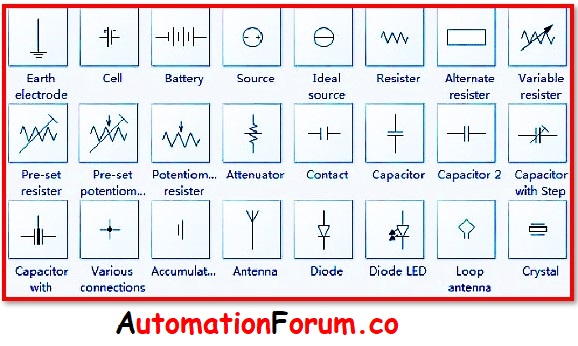
- A resistor is a device that resists the flow of an electric current.To limit the flow of electric current to a given level in electrical circuits, resistors are utilised as passive components. A big amount of electric current will be restricted by resistors with a high resistance value, whereas a small amount of electric current will be restricted by resistors with a low resistance value.
- A capacitor is a device that stores electrical charge and is made up of one or more pairs of conductors that are separated from one another by an insulator.
- An inductor, also known as a reactor, is a passive electrical component that has the ability to store energy in the magnetic field that is produced by the electric current running through it.

An electrical device called an antenna transforms electrical power into radio waves and the other way around.
Below are a few of the most typical basic electrical symbols found in schematic diagrams:
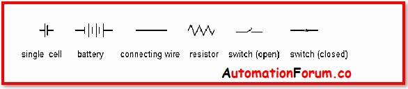
Example:
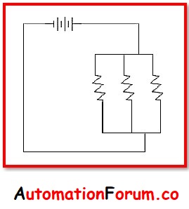
To power a circuit with three light bulbs, a battery pack comprising three D-cells is used.
Each light bulb has a unique resistor symbol to symbolise it. The resistor’s two terminals were connected to each other and to the battery’s two terminals using straight wires.
Battery and resistor are used in this example. After that, join these symbols together using the connector tool. As a result, the final diagram could resemble the image below:

Symbols for Basic Electrical Switches and Relays:
Symbols for switches are shown in the image below.
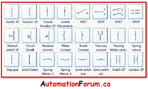
Here, you may find symbols for switches, isolators, circuit breakers, SPST, SPDT, DPST, and more.
An electric circuit can be connected to and disconnected from using a switch. An isolation switch, or isolator, mechanically separates a circuit from the system as needed. A portion of the system is isolated from the remainder by electrical isolators so that maintenance can be done safely.
- A SPST switch is a single-pole, single-throw switch – It functions as an ON/OFF switch. Throws determine how many positions a pole can connect to, and poles determine how many circuits they can be connected to the terminal.
- A SPDT switch is a single-pole, double-throw switch – By changing its position, this switch enables the electricity to flow in either of the two directions.
- A DPST switch is a Double-pole, single-throw switch – Two circuits can be driven by this switch simultaneously.
- A DPDT switch is a double-pole, double-throw switch – By shifting its position, DPDT can connect the four circuits.
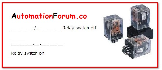
- A Relay switches can control AC loads by applying a DC voltage to the coil.
Example:
A battery pack containing three D-cells is used to power a circuit with three light bulbs.
Basic Symbols for Electrical Transmission Paths:
Symbols for transmission paths like wire, multi-line bus, straight bus, junction, terminal, test point, label, inward flow, and outward flow are shown in the image below:
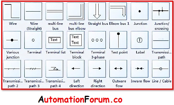
- A wire represents an electrical current-carrying conductor, sometimes known as an electric line, a power line. Connecting the elements in a circuit requires the use of wire.
- A test point is a position inside an electronic circuit that is used to either monitor the state of the circuitry or to inject test signals.
- Inward flow refers to flow of moving inward while outward flow denotes flow of moving outward.
- Electrical Terminals are a type of electrical connector used to transmit electrical current from a grounding or power source to an application. By crimping or soldering to a wire or cable, terminals “terminate.” Electrical terminals include “compression terminals” and “crimped terminals.”