- Introduction to HART and WirelessHART Technology
- Project Planning for WirelessHART Installations
- Integration with Host Systems
- Best Practices for WirelessHART Device Placement
- WirelessHART Device Specification Tips
- WirelessHART Device Installation and Commissioning Process
- Security in HART and WirelessHART Networks: Key Management Strategies
- Efficient Commissioning of HART Devices
- Performing a HART Loop Integrity Check
- Installed Device Record Management
- HART Data Integration Approaches
- Wiring and Installation Guidelines for Wired HART Devices
- Cable Length and Capacitance Considerations
- Test Your Knowledge on Advanced HART Protocol
Introduction to HART and WirelessHART Technology
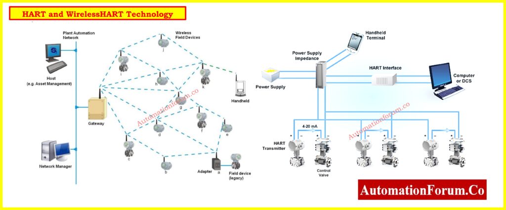
A worldwide known communication standard called HART (Highway Addressable Remote Transducer) Protocol improves the features of conventional 4–20 mA instruments. An extension of the HART Protocol, WirelessHART offers secure and scalable wireless communication, therefore facilitating simple integration of field devices without compromising operational standards or data integrity. Modern process automation has made these technologies essential because of their capacity to provide real-time diagnostics, save wiring costs, and enable predictive maintenance plans.
This complete article makes sure best network reliability, performance, and integration by describing the main procedures for installing and commissioning HART and WirelessHART devices.
Beginner’s Guide: What is HART Protocol?
Project Planning for WirelessHART Installations
Define the Scope of the HART Network
Defining the objective of your WirelessHART network is crucial before any installation runs. Find out whether the program requires
- Process Variable (PV) monitoring for continuous measurement of process parameters like pressure, temperature, flow, or level, therefore enabling real-time visibility. To prevent data dropouts, PV monitoring usually calls for regular communication routes and strong RF coverage.
- For operations where both time and delay are adjustable and control loops are not safety-critical, non-critical control. These uses gain from WirelessHART’s decreased infrastructure cost and adaptability..
- Asset or condition monitoring to gather operational data, temperature, or vibration from rotating equipment, valves, or other assets for maintenance analysis. To save network congestion and increase battery life, these programs could run at lower update rates.
Also following need to be assessed:
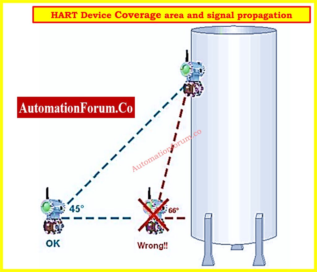
- Coverage area and signal propagation: conduct site surveys to identify possible barriers and RF dead zones. Find physical obstacles such as tanks, walls, or buildings that might block wireless transmission. If you have access, think about employing predictive site modeling technologies. Site coverage should comprise not only the primary process units but also maintenance-accessible areas and connected corridors.
- Network density and interference sources: find possible RF interference from high-frequency machines, Wi-Fi networks, or other wireless devices. Select installation sites with low signal congestion. Validate obvious working channels using spectrum analyzers. Conducting RF scans under normal operational settings will help you to avoid 2.4 GHz overpopulation.
- Types and roles of instruments (primary vs. secondary): Classify instruments according to operational priority:type and function (primary vs. secondary). Faster refresh rates and higher placement priority can be needed for primary instruments. Within the mesh, secondary devices can mostly be routers or repeaters. Early identification of lines that are important for communication helps to give placement priority.
Quick Read: Basics of wirelessHART network protocol
WirelessHART Network Design Considerations
A well-designed WirelessHART network topology guarantees system stability and strong data transfer. Consider about:
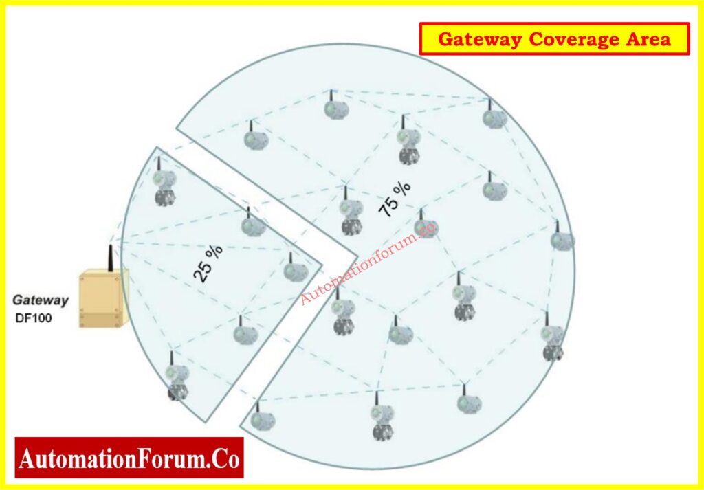
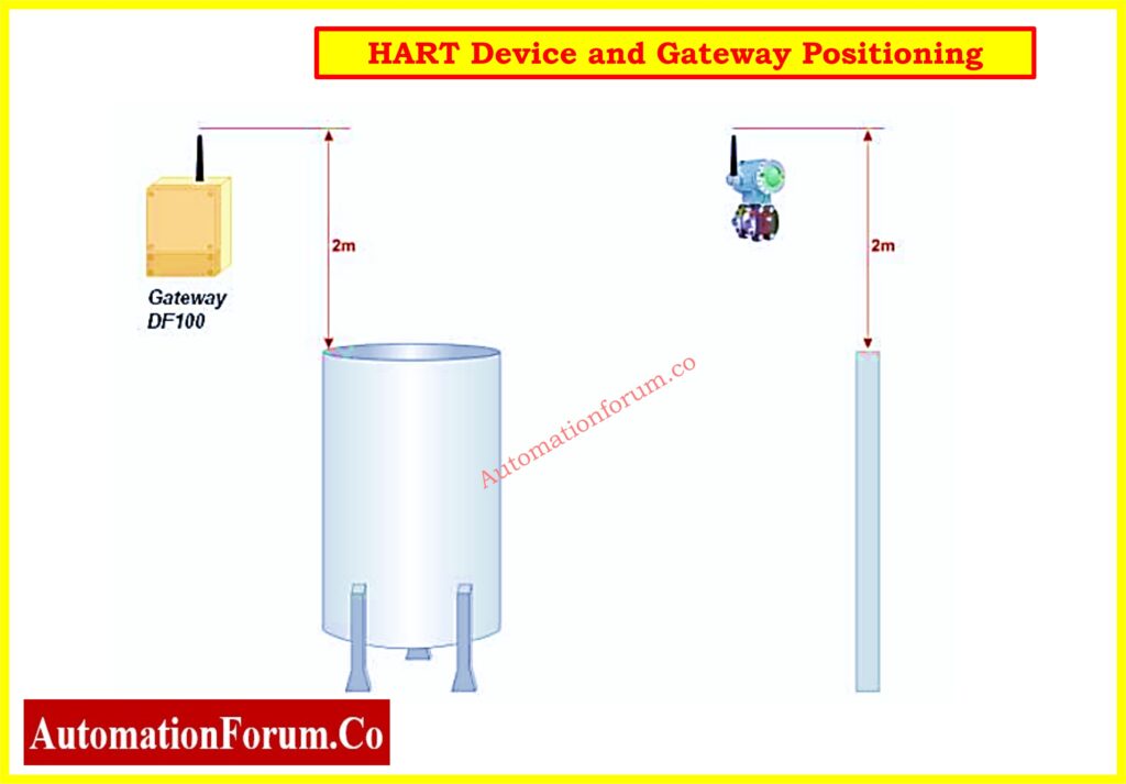
- Gateway positioning: Place the gateway centrally and high so that as many devices as feasible are line-of-sight. Don’t put it close to big metal buildings that could reflect or obstruct signals. Use weatherproof outside enclosures for improved environmental protection if required. Guarantee Ethernet or fiber gateway connectivity to host systems and provide backup power.
- Device update (refresh) rates: Choose device update (refresh) rates depending on application requirements. While consuming more battery power in wireless devices, quicker updates increase reaction time. To maximize performance and battery life, match update rates with process dynamics. For instance, pressure monitoring could require 4s updates whereas vibration monitoring could allow 30s updates.
- Network ID and Join Key management: To avoid overlap, give each WirelessHART network in the facility distinct Network IDs. For uniform security and simple commissioning, use factory-preloaded or standardized join keys. Regularly check access logs and join keys to guarantee network integrity. Keep network credentials in a safe, backed-up configuration control tool.
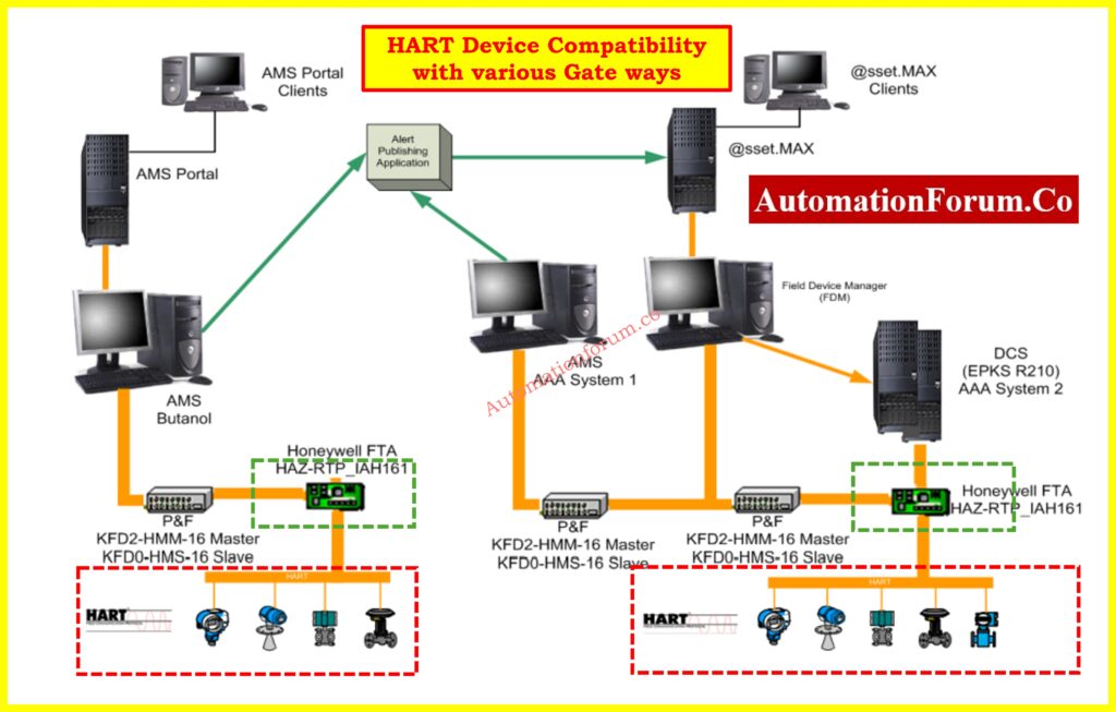
Integration with Host Systems
Protocol Compatibility and Security
It is crucial that WirelessHART devices integrate seamlessly with existing control systems (DCS/PLC).
Use industry-supported protocols including:
- Modbus: perfect for compatibility with legacy control systems and simpler data polling.
- Profibus: Commonly found in European automation systems for both discrete and continuous operations,
- HART-IP or OPC: for sending digital data to higher-level systems including HMIs, asset managers, or history databases.
Use existing configuration tools to simplify device commissioning. WirelessHART has built-in security including:
- 128-bit AES encryption: Ensures secrecy and integrity of transferred data, 128-bit AES encryption.
- Join key authentication: Device identification is verified by join key authentication before it joins the network.
Best Practices for WirelessHART Device Placement
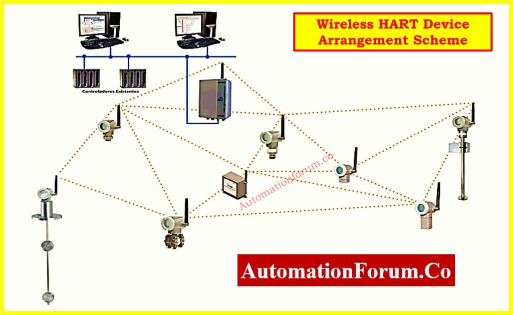
Mesh Network Optimization
WirelessHART runs on a self-healing mesh topology. Devices do not have to directly link to the gateway; rather, they must interact with nearby instruments. Keep these suggestions in mind:
- Use site drawings and scaled plant layouts: Before actual installation, find possible signal blind areas and assist in visualizing ideal device positions. Layout plans should have structural elements such towers, walls, vessels, and pathways.
- Place repeaters in low-signal areas: These improve network dependability by functioning as communication relays in dead zones or between separated clusters. Mains-powered devices can act as permanent repeaters. For temporary installations or low-traffic areas, think about battery-operated repeaters exclusively.
- Employ directional or external antennas: Select antenna kinds appropriate for certain installation requirements. While remote antennas assist in tight or metal enclosures, directional antennas are beneficial for concentrated transmission over great distances. During installation, verify antenna gain and orientation.
- Position devices based on process segmentation: Group devices logically by process units or operational domains. This enables segmenting of networks for troubleshooting or maintenance. Use device naming conventions to indicate segment sites.
- Use elevation for better RF visibility: Install equipment above ground level and away from barriers like walkways, platforms, or pipelines to improve RF visibility using height. Antennas raised above ground level improve network stability and line-of-sight connection. Avoid areas that are shadowed or thermally unstable.
Recommended Placement Criteria
- Mount antennas >0.5 m from vertical surfaces: Mount antennas >0.5 m from vertical surfaces to lower signal reflections and enhance direct line-of-sight connection. Do not put antennas right next to steel structures.
- Install devices at least 1.5 m above ground level: Devices should be installed at least 1.5 m above ground level to reduce interference from metal objects or human traffic and improve mesh dependability.
- Ensure each device has 3+ neighbors: Creates backup routes for dependable communication and network self-healing features. During commissioning, use network visualisation tools to confirm neighbour counts.
- Gateways should maintain at least 5 direct connections: Gateways should keep at least five direct connections; this offers several communication routes for data routing and improves network resilience. Direct connections increase data throughput and lower retransmission delays.
- In large networks, aim for 25% of devices to connect directly to the gateway: This will help to balance network traffic, lower communication delays, and guarantee enough path diversity. Add fixed infrastructure devices if required.
WirelessHART Device Specification Tips
Device Registration and Interoperability
All WirelessHART devices should be registered with the FieldComm Group to ensure design dependability and cross-vendor interoperability. Make sure
- Choosing the right antenna range (available optional high-gain versions)
- Manufacturer provided pre-loaded network ID and join key.
- Expected battery life and device power source compatibility
WirelessHART Device Installation and Commissioning Process
Gateway Installation Steps
- Physically install and power the WirelessHART Gateway
- Starting nearest to the gateway, progressively place devices.
- Check connectivity while expanding the mesh.
Device Configuration Checklist
Every WirelessHART device has to be individually commissioned:
- Set up or turn on the power supply.
- provide the special Network ID
- Enter the safe Network Join Key
- Determine the appropriate update rate based on the criticality of the process..
- Verify network registration at both device and gateway levels
Commissioning and Validation
After deployment:
- Let the network self-optimize for around four hours.
- Make sure each device has at least three stable neighbors.
- Verify 60% path stability across all links
- Increase antennas or add repeaters to help weak links.
Interview Preparation: Understanding WirelessHART: A Comprehensive interview Questions & Answers
Security in HART and WirelessHART Networks: Key Management Strategies
Securing a WirelessHART network calls for appropriate key allocation and access control::
- Used by all devices, Global Join Key
- Personal Keys: Device-specific distinct
- Key Rotation: For greater security, time-based
Factory key assignment might be asked for to simplify deployment.
Efficient Commissioning of HART Devices
Advantages of HART-Based Commissioning
Features such as HART-based commissioning significantly reduce startup time like:
- PC or handheld centralized configuration
- Keeping records as installation
- Diagnostics and loop integrity checks
- Simple integration into asset management systems
Device Verification Procedures
Using software tools or HART communicators:
- Verify device TAG and description.
- Check measurement accuracy and engineering units.
- Verify power levels and update rate.
- Confirm physical configuration data. e.g., materials, ratings
This verification guarantees ISO requirements and safety standards compliance.
How-To Guide: Wiring Diagram for Pressure Transmitter Calibration in Workbench using HART
Performing a HART Loop Integrity Check
Analog and Digital Signal Comparison With HART-enabled transmitters:
- Set a signal at known values using the loop test function
- Verify compatibility between digital PV and analog 4-20 mA signal
- Check secondary device the accuracy (recorders, indicators)
This procedure guarantees electrical integrity and finds any illegal signal transmission offset.
Installed Device Record Management
Documenting HART Device Configuration with many HART tools that allow storage and archiving of configuration data. Benefits include:
- Easier device replacement
- Legal requirements
- Assistance for ISO-certified quality systems
- Historical data access for maintenance planning
HART Data Integration Approaches
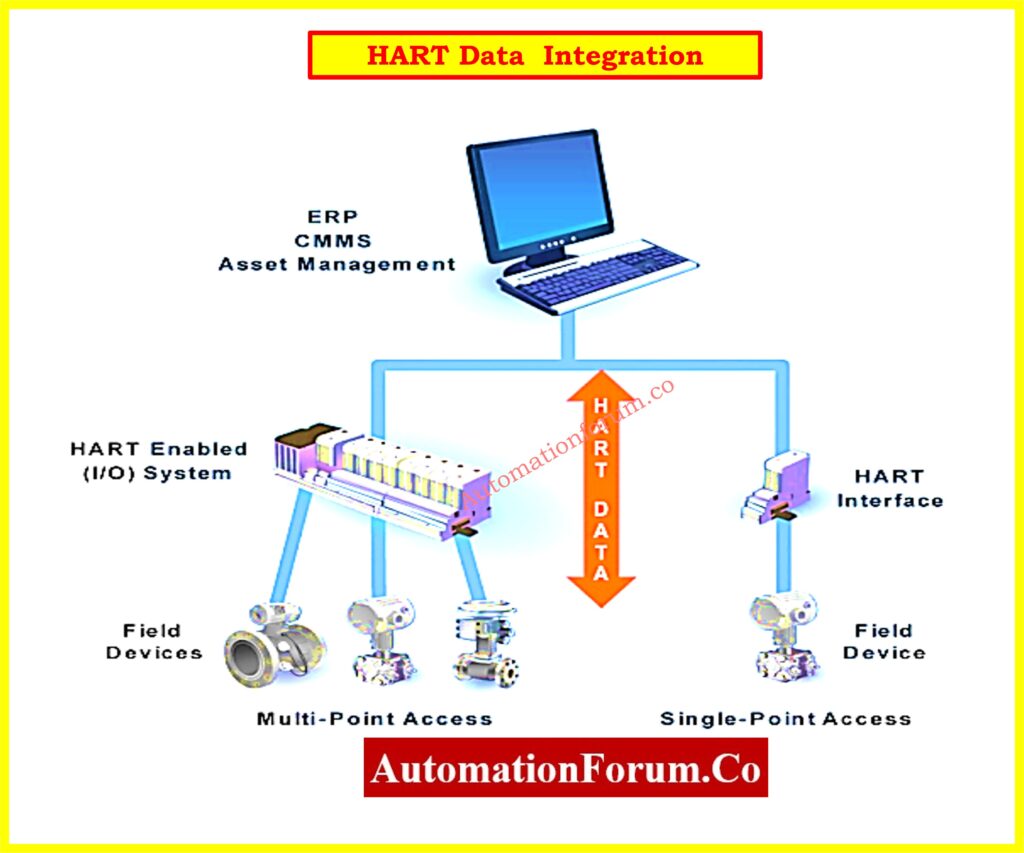
Levels of HART Integration
There are several methods for using HART data:
1. Point-to-Point HART Integration
- The most basic kind uses a handheld or modem for setup
- Gives diagnostics and status without altering infrastructure
2. HART-to-Analog Signal Conversion
- Pull digital HART data and transform it into analog for application in outdated systems
- Allows for incremental updates without complete system overhauls
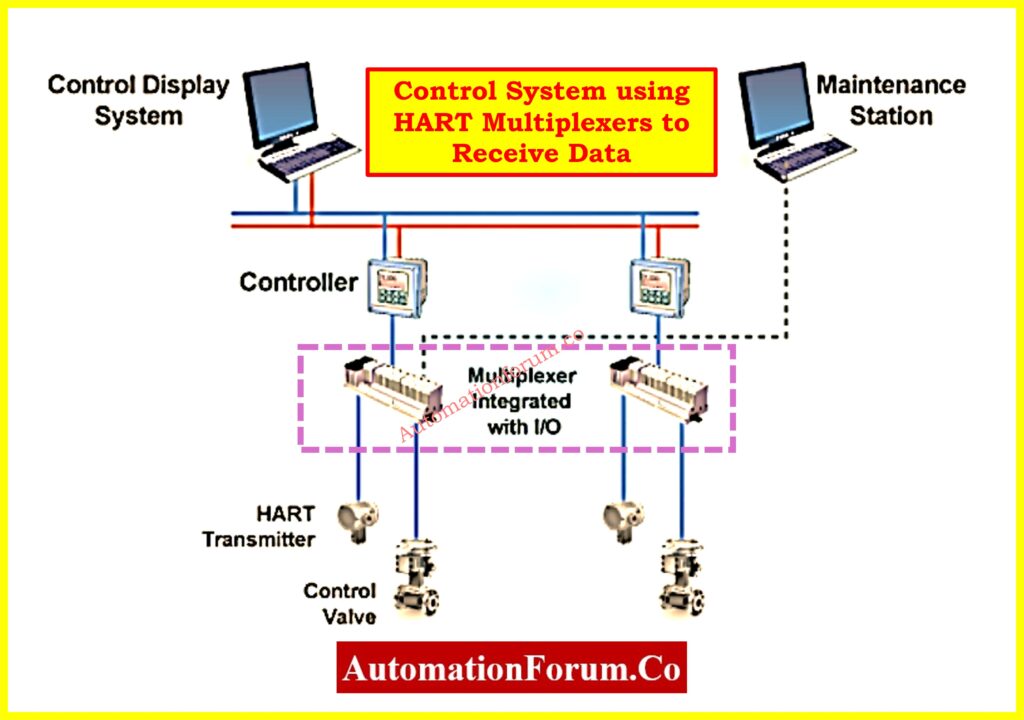
3. Hybrid HART-plus-Analog Integration
- Maintain analog signals to control systems while using HART multiplexers to receive digital data.
- Perfect for condition monitoring and device diagnostics
Explained Simply: What is HART and HART Multiplexer?
4. Full HART Integration
- Use HART enabled Remote or Field I/O modules
- Provides real-time access to device diagnostics and PVs in control system
- By identifying process or device problems early, it facilitates predictive maintenance.
5. HART-to-Plant Network Integration
- Use an OPC server or HART-IP bridge to route HART data to enterprise-level systems.
- Enables process improvement, inventory control, and sophisticated analytics.
Step-by-Step Tutorial: HART transmitter calibration procedure – For pressure transmitter
Wiring and Installation Guidelines for Wired HART Devices
Recommended HART Cabling Practices
Follow these guidelines for wired HART installations:
- referably use individually protected, shielded twisted pair cable
- Minimize electrical noise by means of one-point grounding.
- Select wire gauge depending on run length.
- 0.51 mm (24 AWG) for runs under 1,500 m
- For longer runs, 0.81 mm (20 AWG)
- Do not ground shield at both ends.
- Separate signal ground from junction box or conduit grounding.
Power Supply Requirements
- Standard loop supply voltage: 24V DC
- Make that the voltage supports all anticipated current loads up to 22 mA.
- Think about voltage drops from:
- Cable resistance
- Loop load resistors
- Intrinsically safe barriers (if present)
Power Ripple and Noise Control
To stop HART signal interference:
- Maximum ripple (47 -125 Hz): 0.2 V peak to peak
- Noise maximum: 1.2 mV RMS between 500 Hz and 10 kHz
- Maximum series impedance: 10 ohms
Cable Length and Capacitance Considerations
Total HART loop cable length is affected by:
- Cable capacitance for each foot
- Count of linked HART devices
- Existence of natural safety barriers
Use the following guidelines:
- Use low-capacitance cabling for 3,000 meters max loop length
- Do not go above total allowable capacitance (typ. <200 nF).
- For precise values, see HART Physical Layer Specifications
The table below gives a practical guidance to the maximum permissible cable lengths based on capacitance values and the number of HART devices per segment. With no extra series impedance, the data presumes typical 1.02 mm (18 AWG) shielded twisted-pair cable in non-intrinsically safe (non-IS) settings.
| No. of Network Devices | 20 pf/ft (65 pf/m) | 30 pf/ft (95 pf/m) | 50 pf/ft (160 pf/m) | 70 pf/ft (225 pf/m) |
| 1 | 9,000 ft (2,769 m) | 6,500 ft (2,000 m) | 4,200 ft (1,292 m) | 3,200 ft (985 m) |
| 5 | 8,000 ft (2,462 m) | 5,900 ft (1,815 m) | 3,700 ft (1,138 m) | 2,900 ft (892 m) |
| 10 | 7,000 ft (2,154 m) | 5,200 ft (1,600 m) | 3,300 ft (1,005 m) | 2,500 ft (769 m) |
| 15 | 6,000 ft (1,846 m) | 4,600 ft (1,415 m) | 2,900 ft (884 m) | 2,300 ft (708 m) |
Key Points for Implementation:
- Longer distances are possible with lower capacitance connections. Choosing a 20 pf/ft cable can almost increase the distance over 70 pf/ft.
- More network devices lower permissible cable length. Reassess the cable length and capacitance for every extra device to prevent data loss.
- To reduce electromagnetic interference and transmission deterioration, use shielded twisted pair with suitable grounding.
- For installations over safe lengths, think about employing repeaters or signal boosters, or reworking the segment into several loops.
- For advanced setups and inherently safe conditions, see the HART Physical Layer Specifications.
Always verify the actual installation with a loop simulator or communicator to confirm communication integrity after laying out the cabling.
Optimal device performance and long-term dependability are guaranteed by proper planning, safe device integration, and following HART and WirelessHART installation best practices. HART-based systems improve plant efficiency, cut maintenance, and simplify commissioning with features including diagnostics, loop testing, and real-time setup.
Engineers and technicians may put strong solutions that scale with the needs of modern process sectors by knowing the particular qualities of both wired and wireless HART networks.
Test Your Knowledge on Advanced HART Protocol
Refer the below link to test your understanding in HART and Wireless HART protocol with 25 MCQs with Detailed Explanations