- What is an Inductive Proximity Sensor?
- Understanding Inductive Proximity Sensors
- Advantages of Inductive Proximity Sensors
- How to Select an Inductive Proximity Sensor
- Key Steps to Select an Inductive Proximity Sensor
- Step 1: Understand the Application
- Step 2: Select the Appropriate Housing Design
- Step 3: Determine the Sensing Distance
- Step 4: Determine Mounting Style – Flush vs. Non-Flush
- Step 5: Review Electrical Characteristics
- Step 6: Choose Connection and Cabling Type
- Step 7: Evaluate Special Features and Environmental Requirements
- Tips for Optimal Sensor Selection and Performance
- Why Choose Inductive Proximity Sensors?
- Inductive Proximity Sensor Selection Table
- Inductive Proximity Sensor Selection Guide – Downloadable Excel file
- FAQ on Inductive Proximity Sensor
- What is the maximum range of inductive proximity sensor?
- What is the target size of the inductive proximity sensor?
- What is the principle of inductive proximity sensor?
- Proximity Switch MCQ Challenge: Test Your Knowledge!
A key component of industrial automation, inductive proximity sensors enable precise and consistent identification of metal objects without physical contact. Although the concept of finding a metal product seems easy, choosing the appropriate sensor from a large range of devices could be difficult. Installation conditions, target type, sensor range, electrical properties, and surroundings among other things must be taken into account.
This article provides an organized, comprehensive method for selecting the best inductive proximity sensor for your application.
What is an Inductive Proximity Sensor?
Understanding Inductive Proximity Sensors
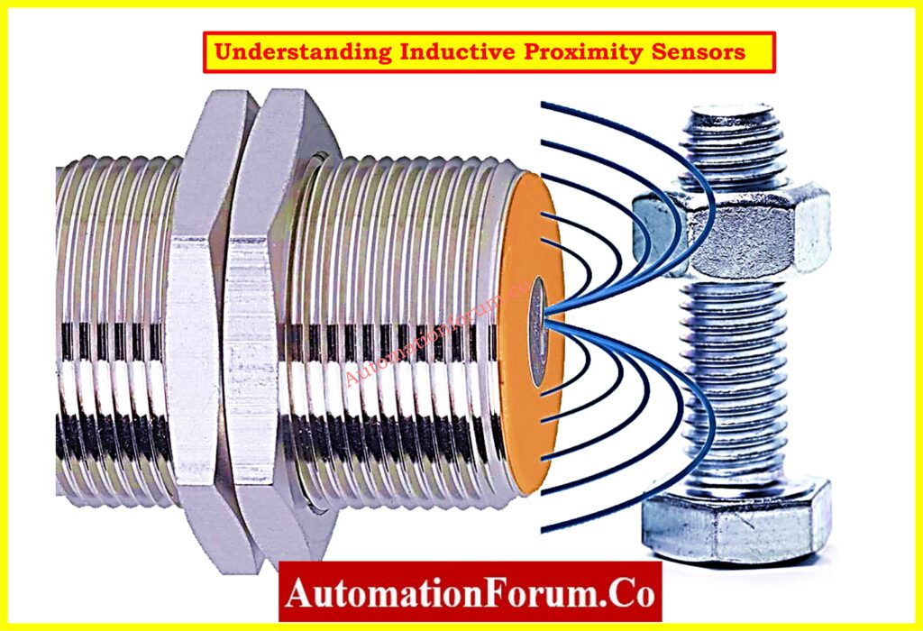
The selection process demands a first step of understanding what inductive proximity sensors are along with their reasons for industrial preference in sensing applications.
Without touching the target inductive sensors identify metallic elements in their operational range. The sensors read metal targets through the operation of an electromagnetic field which allows an oscillator function. A metallic target entering the electromagnetic field makes the device trigger two effects: it creates eddy currents which slow down the oscillator and initiates an output state transition.
Inductive sensors prove useful for harsh industrial conditions due to their reliable operation and strong construction and affordable design. These detectors monitor only metal objects and operate well for the detection of non-ferrous and ferrous materials.
These sensors find their applications in the following situations:
- Position detection (e.g., end-of-travel detection)
- Counting parts on a conveyor
- Speed monitoring in rotary machinery
- Presence/absence detection in automation equipment
This sensor type stands out for its durability in tough settings and provides high precision output across numerous cycles as well as quick reaction times and extended operational existence.
Advantages of Inductive Proximity Sensors
- Such sensors work without touching the target matter which protects both the sensor and sensitive targets from damage.
- These sensors show both resistance to dust along with oil protection and protection from moisture and withstand vibration and mechanical shock.
- The sensor works effectively at high speeds to detect targets that move rapidly or spin in rotary machines.
- The device operates without mechanical components thus delivering extended operational longevity.
- Precision: Repeatable and accurate switching points.
- Low power consumption: Efficient for continuous operation.
- EMC resistance: Operates reliably in electrically noisy environments.
How to Select an Inductive Proximity Sensor
Key Steps to Select an Inductive Proximity Sensor
The following seven strategic steps outline the proper path toward selecting an ideal device:
Step 1: Understand the Application
The initial step in choosing a sensor always starts from the application. You need to clearly define:
- Which materials does the detector system need to identify? The detected material can be steel aluminum or a different sort of metal.
- How large and what form does the target adopt? The detection of targets becomes easier as their size or thickness increases.
- What speed does the moving object exhibit? The frequency along with response speed of sensors should increase when working with fast-moving parts.
- What are the environmental conditions? The sensor needs to face exposure to several elements such as coolant and oil and metal chips and water spray and dust and extreme temperatures.
- How much space does the system provide for mounting? Sensors need to be small or present unconventional geometries to fit into constrained or difficult joint spaces.
Example: In robotic welding the required sensor needs weld-immunity and high durability but in conveyor-based part counting small size with high-frequency capability takes priority.
Step 2: Select the Appropriate Housing Design
The specific physical characteristics of sensors influence their installation convenience as well as their maintenance requirements. Housing types used in sensors mostly consist of:
- The M8, M12, M18 and M30 threaded cylindrical sensor bodies constitute the majority of present-day applications. The standardized housing makes installation possible through simple usage of nuts and brackets.
- The rectangular and cubic forms of sensors are excellent options for applications that need installation in confined areas or attachment to machine surfaces.
- Ring or Slot Sensors serve the purpose of detecting objects that pass through their sensing body while monitoring wire breaks or feeding components.
- Sensors built with heavy-duty housing contain reinforced steel or stainless-steel bodies which protect against high vibration or mechanical stress.
Select a sensor which combines appropriate housing design elements to match your installation requirements and provides adequate mechanical durability.
Step 3: Determine the Sensing Distance
Selection of sensing range needs careful attention to both target size and position due to its role as a critical performance factor. The operating range of inductive sensors extends from 1–80 millimeters while other sensor varieties possess different distance capabilities.
Types of sensing distances:
- Nominal sensing distance (Sn): The theoretical maximum range for ideal conditions.
- Effective sensing distance (Sr): The actual performance in real-world conditions; usually 0.9 to 1.1 × Sn.
- Assured sensing distance (Sa): The minimum guaranteed range to ensure reliable detection.
Tip: Safety margins should always be incorporated into designs. The system design must exclude maximum range detection capabilities for targets because environmental factors can trigger system non-detections..
Furthermore, keep in mind that reduced eddy current generation in non-ferrous metals—aluminum, brass, for example—results in shorter detection ranges. Select a Reduction Factor 1 (RF1) sensor if you want steady performance over metals.
Step 4: Determine Mounting Style – Flush vs. Non-Flush
The detecting field and sensing distance are affected by the mounting type.
- Flush (Shielded) Sensors:
- The sensing face can be integrated level with the mounting surface.
- Because metal surrounds the sensor, the field is focused straight ahead.
- Mechanical protection is provided, but the sensing range is decreased.
- Perfect for installations that are small or need that side interference be avoided.
- Non-Flush (Unshielded) Sensors:
- The sensing face must protrude beyond the mounting surface.
- Offers a more broad, longer detecting field.
- Susceptible to harm or side interference.
- Applied when compact placement is less important than maximal sensing range.
Reminder: To prevent false triggers or interference from close by metal, adhere to manufacturer’s advice on minimum clearance distances.
Top 4 Sensor Selection Errors: 4 Common mistakes in Instrumentation sensor selection
Step 5: Review Electrical Characteristics
Select sensor output and voltage requirements to fit your control system:
- Supply Voltage:
- DC Sensors: Most common; 10–30VDC.
- AC Sensors: 90–250VAC, used in older systems.
- Universal AC/DC Sensors: Offer flexible integration.
- Output Type:
- PNP (sourcing): Outputs +VDC when active. Common in Europe.
- NPN (sinking): Outputs 0VDC when active. Common in Asia.
- Normally Open (NO): Output changes state when a target is present.
- Normally Closed (NC): Output changes state when a target is not present.
- Switching Frequency: Specifies how quickly the sensor can identify on/off changes. Required for quickly moving targets such gears or rotary encoders.
- Response Time: Time lag between target identification and output switching defines response time. Dynamic systems benefit from quicker reactions.
Check: Always consult the device datasheet for maximum current ratings, leakage current, and protective features (e.g., short circuit or reverse polarity protection).
Step 6: Choose Connection and Cabling Type
Sensors provide many connection choices:
- Pre-wired Sensors: Prewired Sensors: Usually two meters length, permanently fastened wires. Excellent environmental sealing. Typical jacket fabrics::
- PVC: General purpose.
- PUR: High flexibility, oil-resistant.
- Quick Disconnect (QD): Allows rapid sensor replacement. Usually with M8 or M12 connections, sensor and cable are distinct. Perfect for regularly maintained systems.
Tip: Your application should guide material selection for cables and connectors. For oily settings, use PUR; for flexible mobility, use STOOW-rated wires.
Step 7: Evaluate Special Features and Environmental Requirements
Depending on the environment or particular requirements, think about other sensor features:
- High IP Ratings (e.g., IP67, IP69K): For water or high-pressure washdown environments.
- Weld-Immune Sensors: Sensors that are weld immune Resist magnetic interference and splatter in welding conditions.
- High Temperature Resistance: Some models operate at +100°C or above.
- ATEX Certification: Explosive gas or dust zones call for ATEX certification.
- Reduction Factor 1 (RF1): Consistent sensing distance over various metals.
- Extended Range Sensors: Provide extended detection ranges for non-contact sensing at further distances.
Especially for safety-critical or export uses, don’t ignore certifications (CE, UL, RoHS, etc.).
Critical Tips for Choosing the Right Pressure Manifold: Key Considerations for Pressure Transmitter Manifold Selection
Tips for Optimal Sensor Selection and Performance
- Don’t overspecify. Don’t select a sensor with a significantly greater sensing distance or better IP rating than required; it could cause higher expenses.
- Test under real circumstances: Before complete deployment, always check sensor performance in your actual application context.
- Think about mechanical protection: Even robust sensors can gain from correct mounting techniques, guards, or brackets.
- Look for certificates Following standards like CE, UL, RoHS guarantees safety and compatibility.
Why Sensor Selection Matters More Than You Think: Importance of Sensor Selection and Placement in Instrumentation
Why Choose Inductive Proximity Sensors?
Several good factors make inductive sensors the favored choice in industrial environments:
- Only detect metal: Ignoring non-metal items like plastic, wood, or glass helps to lower false triggers..
- Durable: Resistant to dirt, oil, dampness, and mechanical shocks.
- Long life: No moving parts to wear out.
- High switching frequency: Effective in high-speed or rotating applications.
- Precise and reliable: Provide consistent switching points.
- Maintenance-free: Their solid-state architecture reduces downtime.
- Cost-effective: Usually less expensive than capacitive or photoelectric sensors.
These benefits provide inductive proximity sensors a reliable method for spotting metal targets in challenging industrial settings.
Detecting metal items in industrial settings usually calls for inductive proximity sensors. Their durability, accuracy, and non-contact operation make them ideal for various uses—from machine tooling and robotics to conveyor systems and packaging lines.
Choosing the correct sensor, therefore, calls for a thorough knowledge of application requirements and sensor parameters. You can make sure your sensor choice results in best performance, less downtime, and long-term dependability by following the six essential steps defining the application, selecting the housing design, deciding the sensing range, assessing mounting and electrical data, choosing connection types, and taking special features into account.
Choosing the correct sensor is not only about detection; it’s also about guaranteeing seamless operation, reducing maintenance, and enhancing general system efficiency.
Unlock Expert Flowmeter Tips Here: Streamlining Your Flowmeter Selection Process: Tips and Insights
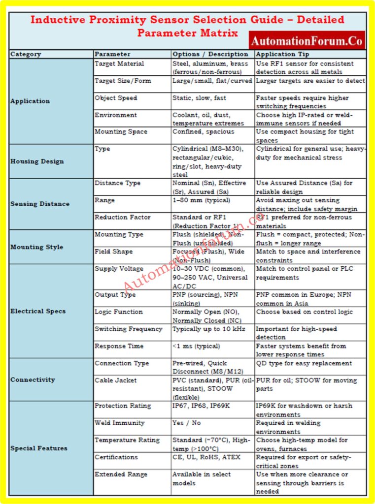
Inductive Proximity Sensor Selection Table
| Category | Parameter | Options / Description | Application Tip |
| Application | Target Material | Steel, aluminum, brass (ferrous/non-ferrous) | Use RF1 sensor for consistent detection across all metals |
| Target Size/Form | Large/small, flat/curved | Larger targets are easier to detect | |
| Object Speed | Static, slow, fast | Faster speeds require higher switching frequencies | |
| Environment | Coolant, oil, dust, temperature extremes | Choose high IP-rated or weld-immune sensors if needed | |
| Mounting Space | Confined, spacious | Use compact housing for tight spaces | |
| Housing Design | Type | Cylindrical (M8–M30), rectangular/cubic, ring/slot, heavy-duty steel | Cylindrical for general use; heavy-duty for mechanical stress |
| Sensing Distance | Distance Type | Nominal (Sn), Effective (Sr), Assured (Sa) | Use Assured Distance (Sa) for reliable design |
| Range | 1–80 mm (typical) | Avoid maxing out sensing distance; include safety margin | |
| Reduction Factor | Standard or RF1 (Reduction Factor 1) | RF1 preferred for non-ferrous materials | |
| Mounting Style | Mounting Type | Flush (shielded), Non-Flush (unshielded) | Flush = compact, protected; Non-flush = longer range |
| Field Shape | Focused (Flush), Wide (Non-Flush) | Match to space and interference constraints | |
| Electrical Specs | Supply Voltage | 10–30 VDC (common), 90–250 VAC, Universal AC/DC | Match to control panel or PLC requirements |
| Output Type | PNP (sourcing), NPN (sinking) | PNP common in Europe; NPN common in Asia | |
| Logic Function | Normally Open (NO), Normally Closed (NC) | Choose based on control logic | |
| Switching Frequency | Typically up to 10 kHz | Important for high-speed detection | |
| Response Time | <1 ms (typical) | Faster systems benefit from lower response times | |
| Connectivity | Connection Type | Pre-wired, Quick Disconnect (M8/M12) | QD type for easy replacement |
| Cable Jacket | PVC (standard), PUR (oil-resistant), STOOW (flexible) | PUR for oil; STOOW for moving parts | |
| Special Features | Protection Rating | IP67, IP68, IP69K | IP69K for washdown or harsh environments |
| Weld Immunity | Yes / No | Required in welding environments | |
| Temperature Rating | Standard (~70°C), High-temp (>100°C) | Choose high-temp model for ovens, furnaces | |
| Certifications | CE, UL, RoHS, ATEX | Required for export or safety-critical zones | |
| Extended Range | Available in select models | Use when more clearance or sensing through barriers is needed |
Inductive Proximity Sensor Selection Guide – Downloadable Excel file
This guide provides a structured overview of key parameters for selecting inductive proximity sensors in various industrial automation applications.
Refer the below link to download:Inductive Proximity Sensor Selection Guide – Detailed Parameter Matrix
FAQ on Inductive Proximity Sensor
What is the maximum range of inductive proximity sensor?
Inductive proximity sensors detect metal objects without contact, with maximum ranges up to 60 mm, depending on sensor type, target material, and mounting conditions.
What is the target size of the inductive proximity sensor?
The standard target size is typically square and matches the sensor’s diameter. e.g., M12 sensor uses a 12×12 mm metallic target for optimal performance.
What is the principle of inductive proximity sensor?
These sensors generate an electromagnetic field; when metal enters the field, eddy currents disturb oscillation, triggering a switch to indicate target presence.
Proximity Switch MCQ Challenge: Test Your Knowledge!
Refer the below link to to test your knowledge in Proximity Switch