- Why Motor Starters Need Protection
- Importance of Low-Level Interlock in Pump Applications
- Field Layout and Sensor Placement
- PLC Ladder Logic for Motor Control with Low-Level Switch Interlock
- Working Principle of the PLC Logic
- I/O Address Mapping and Configuration
- Real-World Scenarios and Simulation
- Safety Interlocks and Protection Features
- Benefits of PLC-Based Motor Starter Control
- FAQ in Low-level Switch in a Pump Control System
Why Motor Starters Need Protection
Motor starters are very important for safely and effectively controlling motors in industrial automation systems. In some procedures, especially those that require tanks. To keep the pump from running dry, which might damage equipment or cause the process to fail, it’s important to connect the motor to a low-level switch.
This article discusses a PLC-based solution for a motor starter with a low-level switch interlock like with a process-specific low-level float switch. We’ll also walk through the system’s hardware layout, electrical schematic, PLC ladder diagram, and its working principle.
Importance of Low-Level Interlock in Pump Applications
The system is meant to control a pump motor that empties a tank. The low-level float switch should only let the motor run if the tank has enough liquid in it. To keep the pump from running dry, it shouldn’t run while the tank is empty.
Key Components and Their Roles
- Emergency Stop – for immediate shutdown.
- Low-Level Switch – to prevent dry run.
- Overload Relay – motor protection.
- PLC Logic – to automate decision-making.
- Indicator Lamps – to show motor status.
Field Layout and Sensor Placement
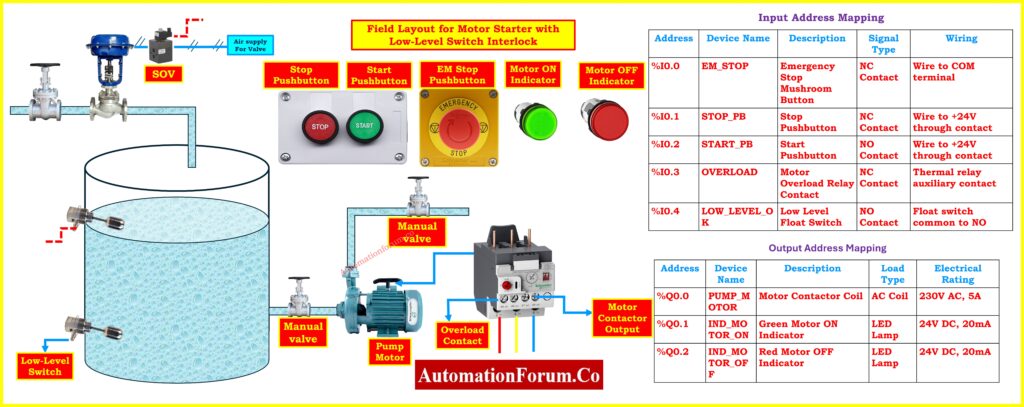
This picture shows how a pump control system is set up in real life, with all of its sensors and actuators.
Real-World Component Layout and Description:
Low-Level Switch (Float Type):
- Installed in the tank.
- Detects when the liquid level drops below a safe limit.
- Prevents pump from running dry.
- Manual operator control.
- Start initiates the motor (if conditions are met).
- Stop halts the motor operation.
Emergency Stop (EM Stop):
- Overrides all controls.
- Immediately stops the motor during emergency.
Motor ON/OFF Indicators:
- Green indicates motor is running.
- Red indicates motor is off or faulted.
Solenoid Valve (SOV):
- Not central to motor logic but shown for air supply control, typically for valve actuation.
Pump Motor:
- Drains liquid from the tank.
- Connected via a manual valve and motor contactor.
Overload Relay:
- Monitors current.
- Trips motor in case of overcurrent, protecting the motor.
Motor Contactor Output:
- Final actuator controlled by the PLC.
- Drives the motor based on logic conditions.
Follow these 6 essential rules for PLC ladder diagram programming: Top 6 Important Rules for PLC Ladder Diagram Programming
Electrical Wiring Schematic for Controlling the Pump Motor
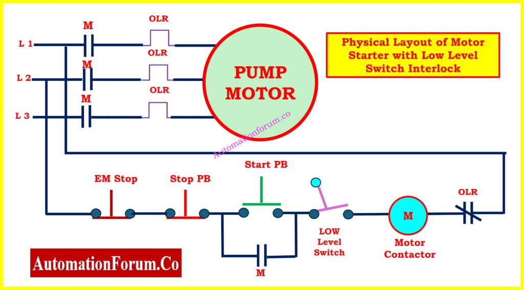
Power and Control Wiring Explanation
- 3-phase power (L1, L2, L3) feeds the motor via contactor.
- Overload Relay (OLR) is connected in each phase to detect excessive current.
- Control Circuit includes:
- Emergency Stop (EM Stop) normally closed.
- Low-Level Switch normally closed (opens when tank is empty).
- The motor contactor is energized only when all conditions are satisfied.
Refer the below link to Learn the difference between NO and NC contacts in PLC logic writing:
Dry Run Protection Using Low-Level Switch:
- If the liquid level falls below the low-level switch, the contact opens, breaking the circuit and stopping the motor on its own.
- You can also break the circuit by hand using the Stop PB or EM Stop.
Start with the basics of rungs and rails in PLC ladder logic: Understanding Rungs and Rails: The Foundation of PLC Ladder Logic
PLC Ladder Logic for Motor Control with Low-Level Switch Interlock
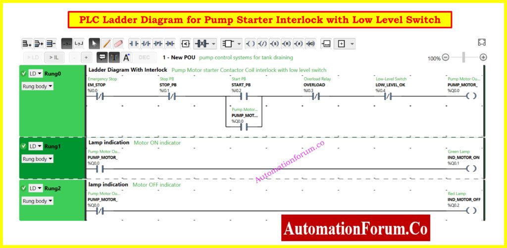
This picture displays the PLC ladder logic that controls the motor starter using a low-level switch interlock.
There are three main rungs in the ladder logic program:
Rung 0: Motor Start/Stop Logic with Interlock
- Emergency Stop (EM_STOP): Normally closed contact (%I0.0)
- Overload Relay (OVERLOAD): Contact that is normally closed (%I0.3)
- Low-Level Switch (LOW_LEVEL_OK): The contact is normally open (%I0.4).
- Pump Motor Output (PUMP_MOTOR): Coil for the motor contactor (%Q0.0)
- All inputs are normally closed (i.e., logic TRUE = input is closed).
- The motor starts only if:
- Emergency stop is not active.
- Overload relay is not tripped.
- Low-level switch is closed (i.e., enough liquid is present).
Get familiar with the basic components of a PLC ladder diagram: Understanding Basic Parts of Ladder Diagram (LD) in PLC Programming
Rung 1 – Motor ON Indicator Logic
- Green Lamp (IND_MOTOR_ON): Activated when pump motor is running (%Q0.1)
Rung 2 – Motor OFF Indicator Logic
- Red Lamp (IND_MOTOR_OFF): Activated when pump motor is stopped (%Q0.2)
Working Principle of the PLC Logic
Start-Up Conditions:
- Is the Emergency Stop inactive?
- Is the Stop PB not pressed?
- Is the Low-Level Switch closed (liquid OK)?
- Is the Overload Relay normal?
- If all are satisfied:
- PLC energizes motor contactor output.
- Motor starts pumping liquid.
- Green lamp turns ON, Red lamp turns OFF.
Tank Empty Shutdown:
If the tank level falls below the low-level switch:
- Switch opens.
- PLC deactivates the contactor.
- Motor stops.
- Red lamp turns ON, Green lamp turns OFF.
Emergency and Fault Handling:
If Overload Relay trips or Emergency Stop is pressed:
- PLC breaks motor output.
- Motor halts immediately.
- Red lamp shows OFF status.
Apply this step-by-step guide for troubleshooting PLC digital outputs: Step-by-Step Procedure for Troubleshooting PLC Digital Outputs
I/O Address Mapping and Configuration
Input Address Mapping:
| Address | Device Name | Description | Signal Type | Wiring |
| %I0.0 | EM_STOP | Emergency Stop Mushroom Button | NC Contact | Wire to COM terminal |
| %I0.1 | STOP_PB | Stop Pushbutton | NC Contact | Wire to +24V through contact |
| %I0.2 | START_PB | Start Pushbutton | NO Contact | Wire to +24V through contact |
| %I0.3 | OVERLOAD | Motor Overload Relay Contact | NC Contact | Thermal relay auxiliary contact |
| %I0.4 | LOW_LEVEL_OK | Low Level Float Switch | NO Contact | Float switch common to NO |
Output Address Mapping:
| Address | Device Name | Description | Load Type | Electrical Rating |
| %Q0.0 | PUMP_MOTOR | Motor Contactor Coil | AC Coil | 230V AC, 5A |
| %Q0.1 | IND_MOTOR_ON | Green Motor ON Indicator | LED Lamp | 24V DC, 20mA |
| %Q0.2 | IND_MOTOR_OFF | Red Motor OFF Indicator | LED Lamp | 24V DC, 20mA |
Real-World Scenarios and Simulation
Scenario 1: Low-Level Switch Active (Safe Operation)
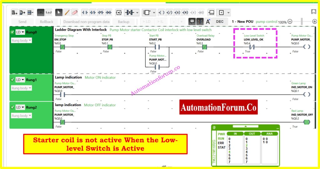
The above mage shows the PLC Simulation as Low Level Switch Active
Operating Conditions:
- Low-Level Switch Status: TRUE (Water level adequate)
- Emergency Stop: FALSE (Not pressed)
- Overload Relay: FALSE (No overload condition)
- Result: Starter coil is NOT ACTIVE – Motor remains OFF
Status Display:
- PWR: Power supply active
- RUN: PLC in run mode
- Green Lamp (Motor ON): OFF
- Red Lamp (Motor OFF): ON
Scenario 2: Low-Level Switch Inactive (Protection Mode)
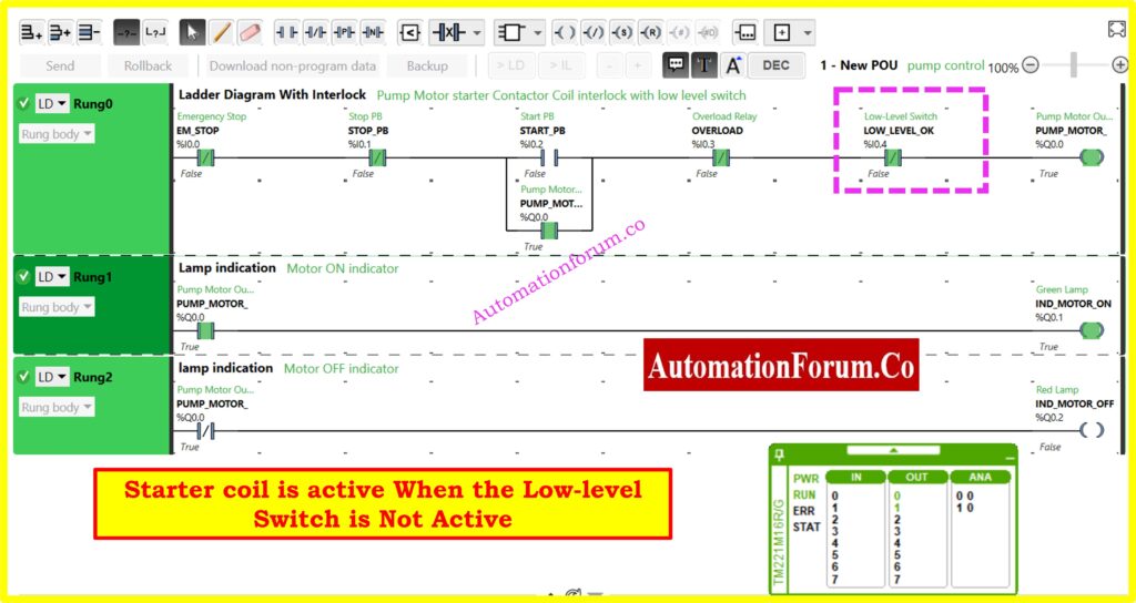
The above image shows the PLC Simulation as Low Level Switch Inactive
Operating Conditions:
- Low-Level Switch Status: FALSE (Water level too low)
- All other conditions: Normal
- Result: Starter coil is ACTIVE – Motor runs (when started)
Critical Safety Feature: When the low-level switch becomes inactive (water level drops), the motor starter circuit is interrupted, preventing pump dry-running and potential damage.
Refer the below link for the Step-by-Step PLC Ladder Logic for Automatic Liquid Mixing Process with Interlocks
Safety Interlocks and Protection Features
Primary Protection Systems:
- Low-Level Protection: Prevents dry running when tank level is insufficient
- Emergency Stop: Immediate system shutdown capability
- Overload Protection: Motor thermal protection via overload relay
- Manual Stop: Operator-controlled normal shutdown
- Start/Stop Control: Maintained contact operation with memory function
Interlock Logic:
The motor can only operate when ALL of the following conditions are met:
- Emergency stop is NOT activated
- Overload relay is NOT tripped
- Low-level switch indicates adequate water level
- Start command has been initiated
Benefits of PLC-Based Motor Starter Control
- Dry Run Prevention: Stops harm to the pump when the tank is empty.
- Automatic Protection: It uses both hardware (OLR) and software (PLC) to keep you safe.
- Remote Control Ready: PLC logic can be upgraded for SCADA or remote control, making it ready for remote control.
- Failsafe: The emergency stop and overload relay give extra layers of safety.
Understand sinking vs sourcing wiring methods for reliable PLC connections: Sinking and Sourcing: Which Connection is Best for Your PLC?
Using a PLC-based motor starter with a low-level switch interlock makes sure that pump motors in tank-based systems work safely, reliably, and automatically. Low-level float switches, on the other hand, let you see how much liquid is available in real time, which is very important for processes that involve moving fluids.
This system is great for water treatment plants, chemical industries, oil storage systems, and many other industrial situations since it protects equipment, saves energy, and is ready for automation.
By using a simple PLC ladder logic, field wiring, and few parts, businesses can keep motors safe and running without having to do anything themselves. This cuts down on downtime and boosts productivity.
Master the use of ON delay and OFF delay timers in PLC programming: Understanding ON Delay and OFF Delay Timers in PLC Programming
FAQ in Low-level Switch in a Pump Control System
What is the function of a low-level switch in a pump control system?
It stops the pump from running dry by stopping motor control logic when the liquid level drops below a safe level.
Why use PLC for motor starter control?
PLCs are great for automation because they are reliable, include interlock safety logic, and can work with SCADA or HMI systems.
Can I simulate this PLC program using TIA Portal or LOGO Soft?
Yes, You can program and simulate ladder logic with TIA Portal or Siemens LOGO! Soft for simple control operations.
Is overload protection handled in PLC logic?
The PLC input is connected to the overload relay. If there is an overload, the PLC utilizes this signal to stop the motor.