- Key Definitions -Scaling Analog Values
- What is Analog Signal Scaling?
- Why is Analog Scaling Important?
- Why PLCs use a Digital Range like 0–27648?
- Analog Scaling Formula
- How Raw Values are Represented in the PLC?
- Scaling Example in a Pressure Control Loop
- Analog Scaling in Practice
- Alarm Considerations and Fault Handling
- NAMUR NE43 and Fault Detection
- Voltage vs. Current Signals in Scaling
- Current vs. Voltage Inputs
- How to Configure a 4-20 mA Analog Input in a PLC
- Soft Tools for Scaling and Diagnostics
- Best Practices for Scaling in PLCs
- What happens if the raw value is out of range?
- Why does my analog input fluctuate even at steady state?
- Test your Knowledge in PLC (Programmable Logic Controller) Knowledge Quiz
In modern industrial automation, analog signals from sensors are the bridge between physical reality and digital control systems. However, the values provided by sensors (like temperature in °C or pressure in bar) are transmitted to PLCs as electrical signals, typically in the form of a 4=20 mA current loop. Analog scaling, a technique used to transform the raw input into relevant engineering units, helps a PLC properly interpret these signals.
The article discusses what scaling is, why it is important, the formulas used, and a practical case study using a pressure control loop..
Key Definitions -Scaling Analog Values
Analog Signal
A continuous signal that reflects changing physical conditions defines an analog signal. Analog signals are often used in industrial automation to monitor temperature, pressure, flow, and level among other variables.
- Current Signal (4-20 mA): Its durability and capacity to find open circuits make it the most used analog signal in industrial settings.
- Voltage Signal (0-10 V or 1-5 V): Usually restricted to short distances, less resistant to noise and voltage drops.
Sensor Output
Transmitters or sensors turn physical variables into analog electrical signals. A pressure transmitter, for instance, might produce 4 mA for 0 bar and 20 mA for 16 bar.
Analog-to-Digital Converter (ADC)
The PLC transforms the analog signal into a digital value by feeding it into an ADC. The digital count or raw value is this.
For instance:
- A Siemens S7-1200 analog input module transforms 4–20 mA into a raw range of 5530–27648..
- The resolution is based on a 15-bit value (0–32,767), but some parts of the range are reserved for diagnostic values (over-range, under-range, open wire).
Engineering Units
Engineering units are human-readable units like °C, bar, %, or m³/h. Analog scaling allows the raw value from a sensor to be interpreted in these terms.
Scaling
In engineering terms, scaling is the process of mathematically converting a raw input signal (digital value) into a physical value. It ensures the PLC correctly reads the real-world signal.
What is Analog Signal Scaling?

In PLCs, scaling is the process of transforming an analog input into useful technical units such as °C, bar, m³/h, etc. The input is typically in digital form following analog-to-digital conversion. It entails converting a signal value from one range (such as 0-27648 counts) to another (such as 0-100°C).
The PLC cannot accurately read or show the physical quantity being measured without appropriate scaling. The PLC has to scale the input to represent real-world pressure levels, for instance, if a pressure sensor is meant to detect 0 to 16 bar and generates a 4–20 mA signal.
Why is Analog Scaling Important?
Improper scaling would render the raw digital values from sensors worthless to operators or control algorithms. Think about the following sequence:
- Sensor reads 10 bar of pressure and produces 12 mA
- PLC gets the signal and interprets it as 9,216 (raw value)
- The system without scaling only sees 9,216 not 10 bar
- Correct scaling allows the system to see and handle 10.0 bar
Accurate scaling enables:
- Accuracy: Without appropriate scaling, control algorithms could run on false information.
- Visualization: SCADA systems display values in engineering units. Scaling aligns the display with reality.
- Alarming: Alarm thresholds are set using scaled values, not raw numbers.
- Historical trending & Diagnostics: Deviations from expected ranges are easier to identify when working with real-world units.
Why PLCs use a Digital Range like 0–27648?
For example, Siemens PLCs use a digital raw range of 0 to 27648 to represent the full-scale 4–20 mA signal. This value corresponds to a 15-bit resolution out of the full 16-bit space (2¹⁵ = 32768). The remaining range is used for diagnostics such as short-circuit or open-wire detection.
This standardization guarantees interoperability across Siemens platforms (S7-1200, S7-1500, etc.), simplifies programming, and enables exact linear scaling of analog input values into engineering units.
For 4–20 mA current loops, Siemens analog input modules usually run a raw input range from 0 to 27648. Here is its mapping:
| Current (mA) | Raw Value |
| 4 mA | 0 |
| 20 mA | 27648 |
Analog Scaling Formula
Usually, analog scaling uses a linear interpolation technique. Consider the ADC’s raw digital input falls inside the range:
- Raw Min = Rmin
- Raw Max = Rmax
The desired engineering units range is thus:
- Eng Min = Emin
- Eng Max = Emax
The scaled engineering value E is then computed as follows:

Where:
- R: Current raw analog input value
- E: Scaled engineering value
How Raw Values are Represented in the PLC?
Every PLC maker has their own scaling format based on the analog-to-digital converter resolution::
- Siemens (15-bit resolution): 0 to 27648 (corresponds to 4–20 mA)
- Allen-Bradley (10-bit or 16-bit): 0 to 1024 or 0 to 32767
- Omron, Mitsubishi, Delta: May have their own range (typically noted in the module’s datasheet)
In Siemens S7-1200, for example:
| Current (mA) | Digital Value |
| 0 mA | 0 |
| 4 mA | 5530 |
| 20 mA | 27648 |
Convert 4–20 mA Signals to 1–5 V and Calculate PLC 16-bit Raw Values Instantly: Calculator for 4-20mA Signal to 1- 5Volt and PLC 16-bit Raw Count Values
Scaling Example in a Pressure Control Loop
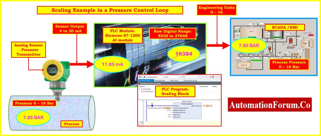
Referring to above displayed image, let us think about a practical situation in which a pressure transmitter tracks steam header pressure and sends this value to a PLC for control and monitoring.
System Overview:
- Sensor Type: Pressure transmitter
- Range: 0 to 16 bar
- Signal Output: 4 to 20 mA
- PLC Module: Siemens S7-1200 AI module
- Raw Digital Range: 5530 to 27648 (for 4–20 mA input)
Objective:
Convert the raw PLC value into a pressure value in bar.
Let’s assume the current raw input from the analog module is 16384.
Step-by-step Scaling Calculation:
Known Parameters:
- R=16384
- Rmin=5530
- Rmax=27648
- Emin=0
- Emax=16
Apply the Formula:

Result:
The process pressure is approximately 7.85 bar.
Refer the below link to understand: How a PLC reads the data from field transmitters?
Analog Scaling in Practice
Connect the Sensor:
- Check whether the analog module is meant for current input.
- See whether configuration resistors or jumpers are needed.
- Consult the module datasheet and follow wiring diagrams.
Input Configuration in Software:
- Specify the input channel kind (e.g., 4–20 mA).
- Set the engineering unit range (e.g., 0–16 bar).
- If there are built-in scaling blocks, such as Siemens SCALE block or FC105, use these.
Testing with a Loop Calibrator:
- Test scaling using a 4–20 mA simulator rather than the real sensor.
- Check HMI or SCADA interface shown values.
Alarm Considerations and Fault Handling
Handling warning thresholds and signal defects is especially important with analog inputs.
Process Alarms
- Alarms for high or low values in temperature, pressure, etc.
- Activated when scaled value exceeds engineering boundaries.
Wire Break Alarms
- The PLC should generate a failure condition if input falls below 3.6 mA or beyond 21.0 mA (NAMUR NE43).
Best Practice
- Always check whether the analog input card supports NE43.
- Before commissioning, test wire break and overcurrent scenarios using current loop simulators.
NAMUR NE43 and Fault Detection
The NAMUR NE43 standard defines ranges for diagnostic reasons when 4–20 mA signals are used:
- < 3.6 mA: Sensor or wiring fault (underrange)
- > 21.0 mA: Sensor fault (overrange)
- 3.8–20.5 mA: Normal operating range
A well-configured PLC will identify whether the analog input exceeds these limitations and activate suitable alerts.
Voltage vs. Current Signals in Scaling
Voltage (0–10 V):
- Zero signal might indicate either “zero measurement” or “broken wire”.
- Not perfect for long distances because of power drop and interference.
Current (4–20 mA):
- Lets you find wire fractures (current drops below 4 mA).
- More noise-resistant and appropriate for industrial settings.
Explore a Collection of Powerful PLC Analog Signal Calculators for Engineers: Collection of PLC Digital Signal Calculators for Industrial Automation
Current vs. Voltage Inputs
| Feature | 4–20 mA Current Loop | 0–10 V Voltage Signal |
| Signal Range | 4–20 mA | 0–10 V |
| Noise Immunity | High | Moderate |
| Wire Break Detection | Yes (if <4 mA) | No (0 V = 0 signal or fault?) |
| Long Distance | Better suited | Limited |
| Power Consumption | Higher | Lower |
Key Takeaway:
Always utilize 4–20 mA for important measurements where fault detection and reliability are important.
How to Configure a 4-20 mA Analog Input in a PLC
Step 1: Electrical Connection
- Connect the sensor per the documentation for the analog input card.
- For voltage-based inputs, a 250 Ω resistor might be used to convert 4-20 mA to 1 – 5 V.
Quickly Calculate the Right Pull-Up Resistor for PLC Digital Inputs and Sensors:Easy Pull-Up Resistor Calculator for PLC Inputs in Discrete Sensor Applications
Step 2: Software Configuration
- Specify hardware configuration input range (e.g., 4-20 mA).
- Scale values in the PLC logic or apply system function blocks.
Step 3: Testing
- Test input scaling prior to live commissioning using a loop calibrator or simulator.
- Use a known signal to validate and then compare the outcome to anticipated engineering values.
Important Tip: To avoid back-feeding problems, be sure to separate the PLC input from the real sensor when emulating a 4-20 mA loop.
Soft Tools for Scaling and Diagnostics
Among the PC-based tools and mobile apps assisting in analog scaling are:
AutomationForum.com: Raw Counts value to Engineering Units
Refer the below link to convert Raw Counts value to Engineering Units
AutomationForum.com: Engineering Units to PLC Raw Counts Conversion Calculator
Refer the below link to convert Engineering Units to PLC Raw Counts
PLC METER (Android): A simple calculator that helps you simulate scaling equations.
Siemens TIA Portal/Step 7: Provides built-in function blocks for scaling.
Best Practices for Scaling in PLCs
- Always refer to the analog card datasheet to determine raw input range.
- Check signal compatibility current vs. voltage before wiring.
- Use software blocks or functions for scaling whenever available.
- Test and validate scaling logic using simulation or calibrators.
- Incorporate fault handling logic for over/under-range detection.
What happens if the raw value is out of range?
A raw analog input value exceeding the specified scaling range often suggests a sensor malfunction, wiring issue, or erroneous scaling configuration. The manufacturer’s PLC handling of this and the implementation of fault detection logic will determine how it handles this. Possible Scenarios are as follows:
Raw value below Rmin (e.g., below 5530 for Siemens 4-20 mA input):
- The PLC shall activate a low fault alert if the signal falls below 3.6 mA per NAMUR NE43.
- Often suggests an over-range situation (signal > 20.5 mA).
Raw value above Rmax (e.g., above 27648 for Siemens):
- Often indicates an over-range condition (signal > 20.5 mA).
- Could result from a miscalibrated sensor, or even a short circuit.
Best Practice:
- Always set up fault detection in the PLC using under/overrange alarm logic.
- Should your system allow NE43 diagnostics, turn it on to obviously find hardware-level problems.
Why does my analog input fluctuate even at steady state?
Common causes of fluctuating analog inputs, sometimes referred to as “signal noise,” at steady-state conditions include numerous different ones:
Electrical Noise / EMI:
- Induced from neighboring power cables, VFDs (Variable Frequency Drives), or switching power sources.
- Poor shielding or ungrounded cables make the problem worse.
Long Cable Runs:
- Voltage dips and pickup noise particularly affect voltage signals (like 0–10 V).
- A bad quality or damaged wire can cause jitter even in current loops (4–20 mA).
Unstable Power Supply to Sensor:
Sensor Sensitivity or Self-Noise:
- Some high-resolution transmitters naturally produce small variations even when stable.
PLC Sampling Rate Too Fast:
- If the PLC scans the input too frequently, small fluctuations are picked up before they can settle.
How to Reduce Fluctuations
- Use shielded twisted pair (STP) cables and ground them at one end only.
- Physically separate analog signal wires from high-voltage power cables.
- Add a low-pass filter in the PLC logic (e.g., a moving average or digital filter).
- Adjust the scan rate or use signal conditioning modules with filtering capabilities.
- Use current loop (4-20 mA) rather than voltage signals for better noise immunity.
Accurate analog scaling is the foundation of reliable industrial control systems. From reading temperatures to maintaining pressure in steam loops, the transformation of a sensor’s analog output into actionable engineering values is essential. By understanding scaling principles, using proper formulas, and verifying configuration with diagnostic tools, engineers ensure safe, efficient, and intelligent automation processes.
Test your Knowledge in PLC (Programmable Logic Controller) Knowledge Quiz
Refer the below link to test your understanding in PLC

 to Standard Liters per Minute (SLPM)")

 to Kg/cm² Pressure Unit Conversion Calculator")

