- Introduction to force balance instruments
- What is a force balance instrument?
- What is the force balance equation?
- Force balance Pneumatic valve positioner mechanism
- Flapper nozzle Pneumatic amplifiers
- Force balance Pneumatic pressure transmitter
- Pneumatic load cells
- What are the advantages of pneumatic instruments?
- What are the disadvantages of pneumatic instruments?
Introduction to force balance instruments
When equal force is applied to both sides of an object then the force is balanced and there won’t be any motion. Pneumatics can be described as the process in which pressurized gas is utilized to create mechanical motion. In a pneumatic system air is the important source for the operation.
What is a force balance instrument?
We can define balanced force as the force that acts on an object from both sides in equal strength. There won’t be any change in the position of the object because the forces are balanced. Any instrument that utilizes this principle is called a force balance instrument. An example of this will be the Pneumatic force balance load cells. The major purpose of utilizing a force balance instrument is that these instruments are self-balanced instruments. The self-balanced instrument will adjust itself according to the sensed quantity
What is the force balance equation?
Imagine that two equal and opposite forces are applied to an object, then the total force that acts on the object will be zero.
F1 and F2 can be considered as the two forces that act on the object in different directions. Then the force on the object F1-F2 =0
Consider an object with a mass of ‘m’ and with a weight of ‘mg’ placed on a bench.
g=Acceleration due to gravity
m = mass
So if the bench applies equal and opposite force on the object and if both the force is equal and opposite then they will cancel each other according to newton’s law. Due to this, the object will stay in its position.
FN is the force applied to the object by the bench also called as normal force
The balanced force equation is FN-mg =0
Force balance Pneumatic valve positioner mechanism
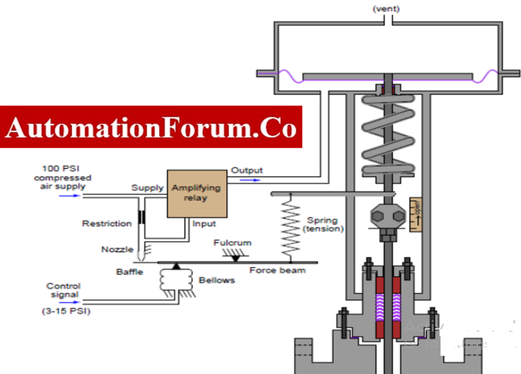
A positioner in a control valve is to set the position of the valve based on the received signal. So, it will change the position of the stem based on the received signal. The above image is an example of a force balance type pneumatic valve position. The valve will receive the control signal from a transducer and this signal will apply a force on the force beam. This will create a force on the nozzle and thereby the relay will be amplified. Due to this, the air pressure to the actuator is increased and this will open the valve by the opening of the stem. When the valve opens it will apply pressure on the force beam. This force will balance the below force and due to this, an equilibrium is created.

Flapper nozzle Pneumatic amplifiers

As we can see in the image air is supplied to one end of the pipe and in this part of the pipe there is an orifice. On the other end of the pipe, there is a nozzle and a flapper. There will be a gap between the nozzle and the flapper based on the input signal. When the flapper moves near the nozzle the air pressure in the pipe will be increased. If the flapper moves away from the nozzle then the air pressure decreases. When the nozzle is open then the flapper won’t be near it and thus the output pressure will be the same as the atmospheric pressure. When the nozzle is in the closed state then the output pressure will be the same as the supply pressure.
Force balance Pneumatic pressure transmitter

In this type of pressure transmitter, a pair of diaphragms are connected on both sides of the DP capsule. The space between these diaphragms is filled with liquid. The differential pressure which is to be measured is applied to both sides of the DP cell. The force bar will take the resulting force and this force bar is in contact with the metallic diaphragm. In case there is any change the force bar will change its position according to the nozzle. This will make a change in the pneumatic output signal. The feedback bellows will determine the new air pressure and also a new force balance will be created by the bar force this is because the bar force is opposed by the force which is developed in the feedback bellows. Due to this, the output signal can be kept in proportion to the pressure detected by the cell.
Pneumatic load cells

As we can see in this figure air is supplied to the chamber and the diaphragm and nozzle are present in it. The force which is to be measured will be applied at the top of the diaphragm because of this force the diaphragm will deflect and the opening of the nozzle will be closed. Due to this, there will be a pressure variation in the chamber and a back pressure will be created due to the shut off of the nozzle opening. This back pressure will make an impact on the diaphragm thus air pressure regulation will take place. This air pressure regulation will be carried out till the diaphragm regains its preloaded position. So the corresponding pressure which is indicated by the pressure gauge during this time will be the measurement of the applied force.
What are the advantages of pneumatic instruments?
- Air is the source so the availability of this source is really high
- It can be channeled easily
- Flexible temperature range
- Clean and safe
- Safe operation of the instruments
What are the disadvantages of pneumatic instruments?
- Air producing device is required
- Mostly pneumatic systems are noisy
- Sensitive to vibrations
- Sensitive to temperature
- Higher operational costs