- Counters
- How does a PLC counter compare to a timer?
- What are some of the benefits of using a counter in a PLC?
- Instruction for Coil-Formatted Counter
- Types of Counter
- Features of Up and Down Counter
- What is negative counter?
- What is meant by counter overflow and underflow bits?
- Counter Counting Sequence
- Representation of PLC Counter from different manufacturer
- Cascade Counters
- Application of PLC Counter
Counters
Typical applications of counters include keeping track of the number of items going through a particular point and determining the number of times a particular activity is carried out.
Preset counters
When the counted total of a preset counter matches the user-entered preset restrictions, the counter is able to regulate an external circuit.
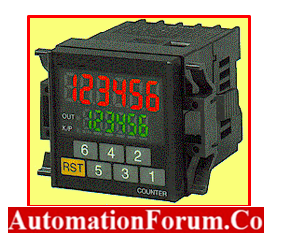
Mechanical Counters
It is possible for programmable counters to perform the same purposes as mechanical counters.
.

- The counter increases by one number whenever the actuating lever is moved over it, and the actuating lever always goes back to its starting position when it is no longer in use.
- A pushbutton on the side of the machine is used to reset everything to its default value of zero.
Electronic Counters
Electronic counters have the ability to count up, count down, or combine the two functions to count both up and down. They must rely on external sources in order to perform counting tasks, such as components moving in front of a sensor or activating a limit switch.
How does a PLC counter compare to a timer?
Similar to timers, PLC counter instructions rely on external or program sources rather than an internal clock to perform their counting functions.
What are some of the benefits of using a counter in a PLC?
- A PLC counter can use a sensor and hence function as a no-contact counter is one of the many advantages of employing this counting method. The possibility that light parts will be unable to move the mechanical counting operator.
- PLC counters typically have retention.
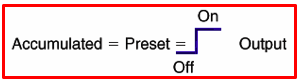
Instruction for Coil-Formatted Counter
When the accumulated count equals the preset count, the output is energized and the counter output is closed. The counter contact can be used as many times as you wish throughout the program as an NO or NC contact.

- The typical counter starts counting at zero and continues until it reaches the intended value, also known as the PRESET value.
- The current value, also known as the accumulated count, is the total that has been accumulated.
Types of Counter
- Counters can count up, count down, or combine the two to count both up and down at the same time.
- Most the counters that are utilized in industry are up-counters, but various applications demand the introduction of down-counters or combination up/down counters. Counters are mainly used in tracking the moving items to a particular point
- Up Counters: Up counters begin counting from a starting value, and when a predetermined count value is reached, an output signal is produced.
- Down Counters: Down counters count down from a starting value, and when a predetermined count value is achieved, an output signal is produced.
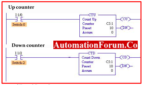
Features of Up and Down Counter
- The count-up counter and the count-down counter are the two primary varieties of PLC counters.
- Counter file name, counter preset value, counter accumulated value, counter count-up bit, and counter done bit for the counter-up counters.
- We have the same bits and values for the counters that are lower in the stack.
- The output’s counter-down bit is the only item that has changed.
What is negative counter?
What is meant by counter overflow and underflow bits?
For count-up counters and count-down counters, respectively, the overflow bit and the underflow bit are used.
- Overflow Bits – The overflow bit is activated when a count-up counter reaches its maximum accumulated value and is then triggered to count up.
- Underflow Bits – The underflow bit is activated when a count-down counter reaches its maximum negative cumulative value and is then triggered to begin counting down.
Up & Down counters are basic types of PLC. It is further it is classified as
- Up/Down Counter
- Ring counter
- Event Counter
- Batch Counter
- Up/Down Counters: Depending on which way the input signal is going, these counters can count either up or down. They are frequently employed in situations where the procedure can go either way.
- Shift Register Counters: Shift register counters of the type called “ring counters” forward the output signal to the following stage after each count. They are utilized in applications where it is necessary to count a series of events.
- Event Counters: Event counters are used to keep track of how frequently a particular process event occurs, such as how frequently a button is pressed.
- Batch counters: Used in applications where a specified amount needs to be generated, batch counters are used to count a specific number of events or activities.
Counter Counting Sequence
- PLC counters typically have a memory.
- On processor restart, the counter will contain the same count that it did at the moment of processor shutdown.
- However, if the reset condition is engaged at the moment of power restoration, the counter can be reset.
PLC counters can be built to either count up to or down from a predetermined value.
Counter Counting Sequence Up Counter
- Every time the rung containing the up-counter is powered, the counter is advanced by one.
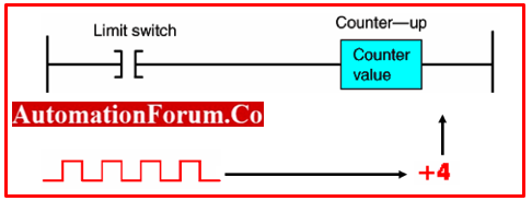
- The counter will keep counting up until its total value equals or exceeds the preset value, at which point an output will be generated.
Counter Counting Sequence Down Counter
- Each time the rung carrying the counter is activated, the down-counter is reduced by one.
- There is always a counter reset available to return the counter’s accumulated value to a specified value.

Representation of PLC Counter from different manufacturer
Allen Bradely’s PLC Counter
The Allen Bradley, PLC Counter is represented as shown. In general there are 3 types. Up Counter – CTU; Down Counter CTD; UP/Down Counter-CUD

In this counter there are following inputs and outputs are
- Count up Input represented as “CU”
- Count Down Input represented as“CD”
- Counter Up/Down represented as “CUD”
- Presetting Counter represented as “Preset”
- Output of Current counter value is represented as “Accum”
The accumulator value is raised by 1 each time there is a pulse at the CTU block’s input.
Siemens PLC Counter
These are the blocks that are utilized in PLC ladder logic as counters. There are some inputs and some outputs on every counter block.
Inputs and Outputs
- S refers to Set Input
- CU refers to Count Up Input
- CD refers toCount Down Input
- PV refers to Preset Counter Value
- R refers to Reset Input Outputs
- Q refers to Counter Status
- CV – Counter Value
- CV BCD – Counter Value in BCD Coded

Feature of PLC counter
- The current Counter Value(CV) will be raised by 1 for each pulse at the Count Up(CU) bit.
- When the Set input (S) receives a pulse, the Presetting Value (PV) is set to the current Counter Value (CV).
- The counter block is reset and the current counter value is set to 0 once more when there is a pulse at the Reset input(R).
- The current Counter Value(CV) will drop by 1 for each pulse at the Count Down(CD) bit.
- When the Set input (S) receives a pulse, the Presetting Value (PV) is set to the current Counter Value (CV).
- The counter block is reset and the current counter value is set to 0 once more when there is a pulse at the Reset input(R).
- The count up and count down routines are also present in this block.
- The current Counter Value (CV) will be increased at each pulse at the Count Up (CU) bit and decreased at each pulse at the Count Down (CD) bit (CV).
- Presetting Value (PV) will be set at the current Counter Value when there is a pulse at the Set input (S) (CV).
- The counter block is reset and the current Counter value is set to 0 once more when there is a pulse at the Reset input(R).
PLC-5 And SLC 500 Count-Up and down Counter

ControlLogix Count-Up Counter Instruction
- The counter address is a data table address in the PLC-5 and SLC 500, but a predefined structure of the data type in ControlLogix.
- The maximum preset and accumulated value for the PLC-5 and SLC 500 is 32,767, while the minimum value is -32,768; for the ControlLogix controller, these numbers are 2,147,438,647 and -2,147,438,648 respectively.
RS Logic Counter

| Name | Commands | Description |
| Count-Up | CTU | With each false-to-true transition, the cumulative value is increased, and it is kept when a power cycle occurs. |
| Count-Down | CTD | Decrements the accumulated value at each false-to-true transition and retains the accumulated value when power cycle occurs |
| Reset | RES | Resets the counter’s accumulated value and status bit. |
| High-Speed Counter | HSC | Counts high-speed pulses coming from a set high-speed controller input. |
Cascade Counters
- Counting events that are more than the number permitted by a counter command may be essential depending on the application.
- Cascading or connecting two counters is one method of achieving this.
Cascading Counters for Extremely Large Counts

- Rung 2 & 3 – Counter C5:1’s done bit resets the counter when it hits 500 and increases counter C5:2 by 1 instead.
- Rung 4 – After 500 times 500, or 250,000 transitions of the count input, the output light goes on.
Application of PLC Counter
1. Parts Counting Program
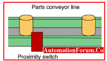
- The total number of components leaving an assembly line for final packaging is counted by counter C5:2.
- Each container must include 10 components.
- Counter C5:1 sets bit B3/1 to start the box closure sequence when 10 components are found.
- The total number of packets filled each day is counted by counter C5:3.
- The daily total part and package count is reset to zero using a pushbutton.

2. In-Process Monitoring System

- Raw parts are fed into the in-feed sensor to start the operation, and each part generates an up count.
- After processing, finished parts that arrive at the out-feed sensor create down counts, so the counter’s accumulated count continuously represents the number of parts that are still being processed.
- The system is absolutely devoid of components prior to startup, and the counter is manually reset to zero.

3. Parking Garage Counter Program

- When an automobile pulls in, it activates the up-counter output command and raises the total count by 1.
- When an automobile drives away, it activates the down-counter output instruction and reduces the total count by 1 as it does so.
- The accumulated amount will be the same in both the up- and down-counters because they share the same address.
- When the total value reaches a certain threshold, the counter output is activated, illuminating the Full indication.
Case 1 : Assuming car slot vacancy of 100 nos. When the last car enters in indication of “FULL”

Case 2 : When a car goes out, after the Full the indication changes to “VACANCY”
