Control panel is a cabinet which contains electrical components to control the motors and equipments.
CABLES
Cables are used for the interconnection. Two types of cables are used. Power cable and control cable.
1. Power cables (which is used to connect the motor to panel component and panel to main supply)
2. Control cables (which is used to connect the control circuits)
BUS BAR
BUS BAR
Incoming supply is connected to bus bar and distributed from bus bar. It is normally made by Aluminum.
MCB (Miniature Circuit Breakers)
MCB is a protecting device. It is used before the feeder. This should be selected according to the capacity of the feeder
MCCB (Mould Case Circuit Breaker)
In most of the cases the MCCB used as an incomer for higher capacity feeders for better protection
ELCB (Earth Leakage Circuit Breaker)
The ELCB is also known as RCCB. The device used for the protection against the earth leakage current and residual current. It should be fixed before the incomer
INCOMER
The basic supply will connected to this incomer. It also called as SFU(Switch Fuse Unit). It contains one handle with fuse unit. Once it is turned ON the supply will pass to the next stage through fuse if any major fault occurs in side panel board, it will trip and it isolate supply.
SELECTOR SWITCH
Selector is switch is used for ON/OFF purpose and for selecting the mode of operation like auto/manual.
Starters are used for starting the motors safely. Mainly two types of starters are there. DOL starters and Start to delta. Dol starter is enough for the motors with power less than 10 hp.
OVER LOAD RELAY
Over load relay is for the protection of motor from the over load. It senses the load current and trips if it exceeds the limit. Current limit has to be set manually. It should be 80% of the full load current.
TIMER
Operation of timer is similar to relay. But a delay is there for actuation. We can set the time delay manually according to our requirement. It is very much essential for start to delta conversion.
CONTACTOR
Contactor is an essential component in the control panel. It actuates when the signal from the controller (PLC, Relay logic) comes. It is similar to relay. It is costlier than relay. It is used for a higher load.
Insrumentation construction engineering is a handbook for instrumenation engineers who is working in construction field.Following chapters are included in the e-book.
Drawings which represents installation standards is called hook up drawings. With hook-up drawings, engineer can understand how an instrument to be installed in the plant. With hook-up drawing, we can calculate the material requirement. Two types of hook up drawings are there.
1. Pneumatic hookup.
It is independent of process connection. Pneumatic hookup is basically Tubing/piping
2. Process hookup.
Here instruments are directly connected to process line.
P&ID: Schematic illustration of instruments and their interconnection is called P&ID.
PFD:Process flow diagram.PFD gives an overview of the plant process.PFD is a simplified version of P&ID.
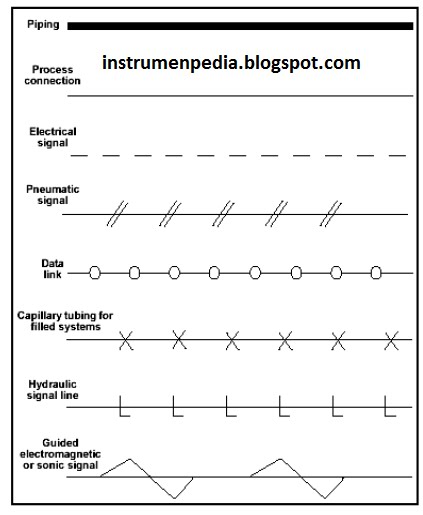
Symbols,circles and lines are used to represent instrument and their interconnection.For identifying instruments and pipe lines tag numbers are used.For reading P&ID(Piping & instrument diagarm) one must be familiar with standard instrument symbols and standard identification letter.
Instrument Location:The presence or absence of a line determines the location of the physical device.Some instruments are a part of a distributed control system where a specific controller or indicator can be selected from many others but shown in one location.
Piping and connection symbols:These symbols are used to identify how the instruments in the process connect to each other.And what type of singnal is being used.
Instrument location layout is a layout which indicates the exact location of instrument/junction box, trench/trays etc.
Trench and duct is the path for primary cable and tray is the path for secondary cables. A tray is either made of metals or FRP (Fiber reinforced plastic).
What is Junction box and Junction box location drawing?
A junction box is an intermediate between instrument and control panel. A junction box is an electrical box which contains terminal blocks. The cables from the instruments come to one side of the terminal block and from the other end, it goes to the control panel. As I mentioned in previous post cables from the control panel is called primary cables. Usually, multicore cables are used as primary cable. Cables to the instruments are called primary cables. Usually, single core cables are used as secondary cable.
Terminal block
Typical example of a junction box
What is the purpose of a Junction box?
Purpose of a Junction box is to give convenience and protection for cabling between instrument and control panel. In maintenance point of view, a junction box is very much important. It helps very much in troubleshooting. Below I am giving an example of Junction box location drawing.For proper entry of cables to the JB, Jb arches are used. Cables are entering to the JB through cable glands. The cable gland is used for the proper placing of cable. Different types of cable glands are available.
As i said in my previous post here i am going to explain about the documents which is essential for instrument engineers.Four types of documents are mainly used by instrumentation engineers.
Instrument index.
An instrument index is a consolidated list of all instruments which is used in the plant.Instrument index is made
according to the P&ID.In this all instruments tags are listed in an orderly manner.It consists of following details.
a).Type of instrument.
b).Location of an instrument.
c).Installation standard.
Data sheet.
Data sheet is a document which contains information about the performance and characteristics of an instrument.An example for data sheet is given below.
Cable schedule.
We can categorise the cables in to two type.1.Primary cables and 2.Secondary cables.
1.Primary cables
Cable which is laid between junction box and control room is called primary cable.
2.Secondary cables.
These cable is laid between instrument and junction box.
Cable schedule gives the details about from where the cable has to come and where it has to go.For easiness each cable is tagged and the details is mentioned in cable schedule.
Bill of material.
Bill of material is a list of raw material required.For impulse piping lot of materials are required.Eg: elbows,nipples,tees,coupling etc..By referring bill of material an engineer could get an idea about the material
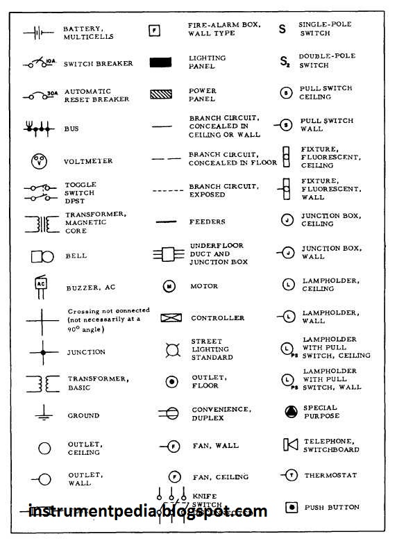
As an instrumentation or electrical engineer,one must have to know read the electrical drawings.From my experience i can say no one might not hav taught you to read the drawings in your class room.I want to make a difference here.So i am giving the list of electrical symbols.
An electric circuit is made up of many circuit components joined together to provide a closed path that allows electricity to flow. An electrical circuit element is the mathematical representation of an electrical device and is entirely defined by the relationship between voltage and current. As a circuit element is the most fundamental component, it cannot be separated into other devices.
Three fundamental circuit components
Resistor
Inductor
Capacitor
What is the units of electrical elements?
Elements
Units
Voltage
Volt (V)
Electric Current
Ampere (A)
Resistor
Ohm (?)
Inductor
Henry (H)
Capacitor
Farad (F)
Power
Watt (W)
Energy
Joule (J)
Capacitor – Definition, Formula & Types
What is a Capacitor?
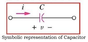
A capacitor is an electrical circuit component that has the capacity to store electrical energy in the form of an electric field. Capacitance is the characteristic of a capacitor that allows it to store electrical energy. Symbolic representation of capacitor is shown below.
Symbolic representation of Capacitor:
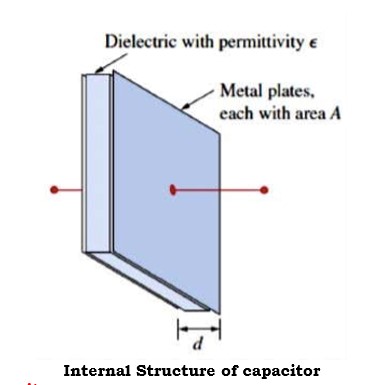
Two metallic plates are separated by an insulating substance to form a basic capacitor. This insulating substance, which is called as dielectric, holds electrical energy in the form of an electric field. There are various varieties of capacitors, such as paper capacitors, air capacitors, mica capacitors, ceramic capacitors, electrolytic capacitors, etc., depending on the dielectric material employed. The structure of capacitor is shown below.
Internal Structure of capacitor:
Formula of Capacitance:
Capacitance is calculated as
where
– The permittivity of the dielectric material between the plates (F/m),
A – The surface area of each plate (m2 ), D is the distance between the plates (m)
Capacitance of a capacitor is the ratio of the charge (q) per plate to the applied voltage (v) can also be said C = q/v
Capacitor is a circuit device whose terminal voltage directly proportional to integral of current with respect to time.
Instantaneous power delivered to the capacitor:
Stored energy in the capacitor:
Therefore
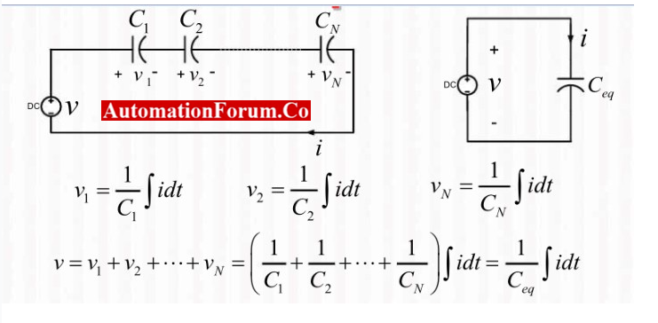
Combination of capacitors:
Either the capacitors can be connected in series or parallel.Capacitors in parallel are added together – capacitance increases.In series capacitance is reduced.
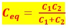
Capacitors in series:
Therefore, equivalent series capacitance is,
Capacitors in parallel:
Therefore, equivalent parallel capacitance is,
Types of Capacitors:
Capacitors are classified based on their polarity as,
Polarized Capacitors
Non-Polarized Capacitors
A polarized capacitor is one that has fixed positive and negative polarity markings on its terminals and a fixed terminal polarity. So, only DC circuits can use polarized capacitors. Because the terminal polarity of a non-polarized capacitor is not fixed, it can also be utilized in AC circuits.
Depending on the change in capacitance, the capacitors may be of two types namely fixed capacitors and variable capacitors.
Resistor – Definition, Formulae & Types
What is a Resistor?
A resistor is an electrical circuit component that places electrical friction or resistance in the path of an electric current. Resistance is the property of opposing the flow of current in a circuit. A resistor’s resistance is indicated by the symbol R and expressed in Ohms (?).
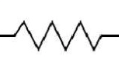
SYMBOL
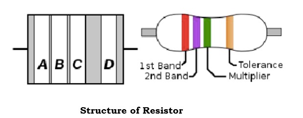
Structure of Resistor:
The resistor structure is shown above. In the above structure, we have 4 different bands namely A, B, C & D.
First band is A which is resistance first significant figure value
Second band is B which is the second significant figure
Third band is C which is the decimal multiplier
Fourth band is D if present that indicates tolerance of value in percent (no color means 20 %)
The value of resistance can be calculated by standard color code per EN60062:2005 is as follows:
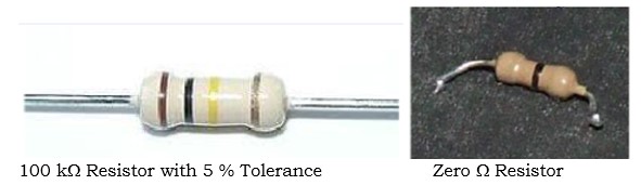
From the above table the resistor value can be read from left to right. The below shown is brown, black, yellow, gold then the resistor value is 100KW with 5% tolerance.
Zero ohm resistors, which has a single black band.These are lengths of wire wrapped in a resistor shaped body that can be substituted for another resistor value in automatic insertion equipment.
Formula of Resistance:
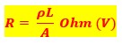
The resistance can be calculated as
Where, r is resistivity of material (W-m), L is length of conductor (m), A is area of cross-section (m2)
The voltage applied across a resistor directly affects the current flowing through it. An element is referred to as a resistor, in voltage-current relationship if the voltage across it is directly proportional to the current through it.
As Resistance (R)
where V is the applied voltage (v) and I is electric current (A)
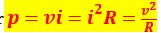
Instantaneous Power delivered to the Resistor:
Stored energy in the Resistor:
Combination of resistors:
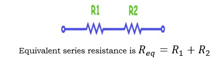
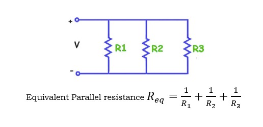
Resistors can be connected in either series or Parallel. Resistors in series arrangement sum up together and resistance increases. In parallel arrangement resistance is reduced.
Resistors in series:
Resistors in parallel:
What are the types of Resistors?
Based on several criteria, resistors can be categorized into various categories. According to Ohm’s law, resistors can be divided into the two categories.
Linear Resistors
Non-Linear Resistors
Linear resistors, also known as ohmic resistors, are resistors that adhere to Ohm’s law. The term “non-linear resistor” or “unohmic resistor” is used when a resistor does not follow Ohm’s law.
Depending on the changing of resistance value, there are two types of resistors
Fixed Resistors
Variable Resistors
Resistors whose value remains constant and never be changed are known as fixed resistors. Resistors whose value can be varied are known variable resistors.
What is a resistor used for?
The amount of electrical current that can flow through a circuit in an electronic device is controlled or limited by a resistor.
What is theory behind resistor?
Circuit components called resistors obstruct the flow of current. A pure resistor generates heat from electrical energy. This energy is transformed into light, motion, heat, and other types of energy via components like resistors.
How a resistor work in circuit?
Resistors in the circuits stop an excessively high current from harming the breadboard, wires, battery. Also, the resistor regulates the electron flow.
What is the unit of resistance?
The unit of resistance is ohm.
Inductor– Definition, Formula & Types
What is an Inductor?
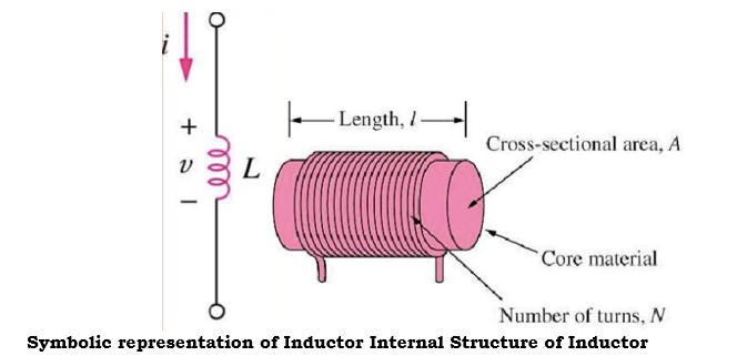
An inductor is essentially a wire with a limited length that has been wound into a coil. An inductor is another fundamental component of a circuit that is used to add inductance to an electrical or electronic circuit. An inductor prevents any change in the electric current. The symbolic representation & internal structure of inductor is shown below.
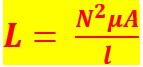
Formula of Inductance:
Inductance can be calculated by
where N is number of turns in coil, A is the cross-sectional area of coil, m2, l is the length of the coil (m) and m is the permeability of the core material H/m.
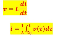
In terms of the relationship between voltage and current, an element with two terminals whose terminal voltage is directly proportional to the derivative of current with respect to time is known as an inductor.
The voltage across the inductor would be zero if the current through it remained constant. An inductor using DC acts like a short-circuit coil. An inductor’s current cannot abruptly change. The ability of an inductor to store a limited amount of energy in the form of a magnetic field is a one specific characteristic. An ideal inductor only stores energy rather than releasing it.
Instantaneous power delivered to the Inductor:
Stored energy in the Inductor:
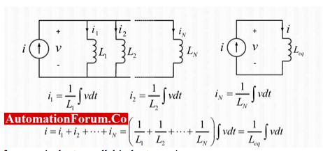
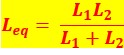
Combination of Inductors:
Inductors can be connected in either series or Parallel. Inductors in series are added together – inductance increases. In parallel inductance is reduced.
Ohm’s law(which should be familiar) is a very useful rule. Note that it only applies to resistive loads however. The impedance of other passive components may vary with (e.g.) frequency (e.g. capacitors) and many components do not obey this rule at all (diodes, transistors etc.).
Resistance determines how much charge flows per second when a voltage is applied. Resistance is lower if the material the device is made from has many charges (normally electrons) init and if the charges can move easily through the material. Both of these depend on temperature.
Kirchoff’s law, which is common sense, states that the sum of currents at a join in wires is always zero, i.e. any charge (current is a flow of charge) which goes in must come out somewhere.
Ohm’s Law
V = I x R
This is only true for resistive loads. Most loads are more complex than this.
In general:
V = I x Z where Z is the impedance of the load.
This may depend (forexample) on the frequency of an A.C. signal.
Kirchhoff’s Current law
What goes in, comes out.
A simple application:
Potential divider
There is a tacit assumption here that no current flows in the output


