What is a Contactor?
A contactor is an electromagnetic switch that is used to turn on and off an electrical circuit. It’s also a device that can be controlled from a distance. It should be able to make, carry, and break currents in normal and operational overload circumstances. It’s closest to the load centre. It is regarded as a unique sort of relay.
The main difference between a contactor and a relay is that:
- The contactor is utilised in applications that require a larger current carrying capacity
- The relay is used in situations that require a lower current carrying capacity.
Contactors are small and easy to install in the field. These electrical devices usually have many contacts. When the contactor coil is powered, these contacts are generally open and deliver operating power to the load. For the most part, contactors are used to regulate electric motors.
Contactors can handle currents ranging from a few amperes to thousands of amperes, and voltages ranging from 24 VDC to thousands of volts. Furthermore, these electrical gadgets are available in a variety of sizes, ranging from hand-held to metre or yard-long.
High-current loads are the most typical use for contactors. Contactors are notable for their capacity to handle currents in excess of 5000 amperes and high power in excess of 100 kW. When a large motor current is interrupted, arcs form. A contactor can help to manage and decrease these arcs.
For example:
- Motors,
- Lights,
- Capacitors,
- Heaters, and
- Furnaces
can all be switched using this method.
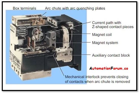
Construction of a Contactor:
A contactor is made up of three subsystems
- System of electromagnetism
- Enclosure (or)Housing
- Arc and contact quenching system
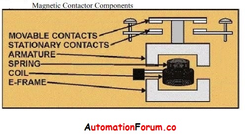
System of electromagnetism:
This is the most important part of the contactor. The coil or electromagnet of the contactor provides the necessary driving force to close the connections. An enclosure protects the coil or electromagnet as well as the contacts.
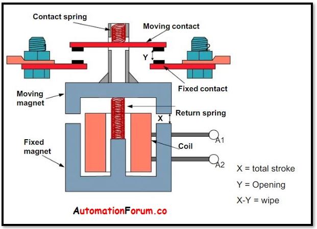
In a contactor, the coil provides the driving force that closes the contacts. It resembles an electromagnet because it has a coil twisted around an electromagnetic core. The coil is made up of two parts:
| A Permanent one and |
| A Moveable one connected by a spring |
A spring return mechanism is created using this arrangement.
The moveable portion is attached to an armature, which is a rod. Both contacts connect when the coil’s force exceeds the spring’s force. The connections disconnect when the spring force exceeds the coil force.
The contactor coil’s input can be either AC or DC. This current comes from the contactor’s external control circuit and is used to stimulate the electromagnetic core.
- The electromagnetic core material for AC contactors is soft laminated iron. It aids in the reduction of eddy current loss.
- Solid steel is used for the electromagnetic core in DC contactors since eddy current is not a concern.
Enclosure (or)Housing:
Contactors have an enclosure similar to those used in other applications, which provides insulation and protection against personnel touching the contacts.
- Polycarbonate,
- polyester,
- Nylon 6,
- Bakelite,
- thermosetting polymers, and
- other materials
are used to construct the protective enclosure. In most cases, an extra enclosure is added to the open-frame contactor to protect it from severe weather, explosion threats, dust, and oil.
Arc and contact quenching system:
Another key component of this electrical device is the contacts. The contacts are in charge of the contactor’s current carrying task. In a contactor, there are three sorts of contacts:
- contact springs,
- auxiliary contacts, and
- power contacts.
Each sort of contact has a distinct function.
High welding resistance and consistent arc resistance are required for forming connections. Erosion and mechanical stress should not be a problem for the material. Silver tin oxide is used in high current and DC applications, while silver nickel and silver cadmium oxide are used in low current applications.
Operation of the Contactor:
An electromagnetic field is created whenever the electromagnetic coil is powered. The metallic rod (armature) is drawn towards the gap in the hollow cylindrical magnet by the electromagnetic field.
The moveable half of a split electromagnet is attracted to the fixed electromagnet in contactors with split electromagnets. The contacts are closed as a result of this action. As long as the electromagnet is stimulated, the connections remain closed. The spring pushes the movable contact back to its usual position when the coil is de-energized. To open and close contacts quickly, the contacts are kept spring loaded. As it rapidly makes contact with the fixed contacts, moving contacts may bounce. To reduce bouncing and improve reliability, twin or bifurcated contacts might be employed.
The coil’s excitation power can be AC, DC (available in a variety of voltage ranges from 12VAC/ 12VDC to 690VAC), or even universal. Universal coils are those that can work with both AC and DC voltages. During switching operations, the coil draws a modest quantity of electricity. Economiser circuits are used to lower the contactor’s power consumption when it is in operation. Shade coils are used in contactors with AC coils. They might buzz if the alternating current does not cross zero. Shading coils prevent chattering by delaying demagnetization of the magnetic core. DC coils do not require shading because the flux produced is constant.
Different Types of Contactors:
There are three different types of Contactors, they are:
1. Knife Blade Switch Contactor
2. Manual Controller, and
3. Magnetic Contactor,
Knife Blade Switch Contactor:
It was almost certainly the first contactor used to regulate (start or stop) electric motors. The switch was made out of a metal strip that dropped into a contact. This switch had a lever that could be used to pull the switch down or up. The knife blade switch had to be levelled into the closed position by standing next to it back then.
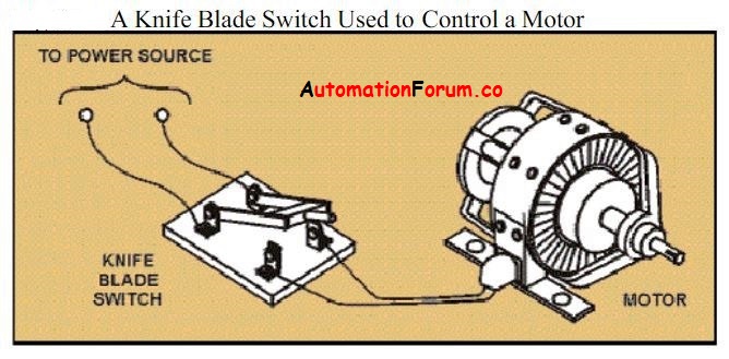
There was, however, an issue with this way of switching. Because it was impossible to manually open and close the switch quickly enough to avoid arcing, this method caused the contacts to wear out quickly.
As a result, the soft copper switches began to corrode, making them more susceptible to moisture and filth. The size of the motors grew greater throughout time, necessitating the use of larger currents to operate them. As a result, operating such high current carrying switches could be dangerous, posing a severe safety hazard. Despite a number of technical advances, the knife blade switch was never fully developed due to the challenges and risks of dangerous operation as well as the contacts’ short life.
Manual Controller:
The following are some of the features of a manual controller:
- It’s easy to use.
- Unit that is not visible and is appropriately wrapped
- Smaller in size physically
- Double-break contacts have been installed in place of single-break connections.
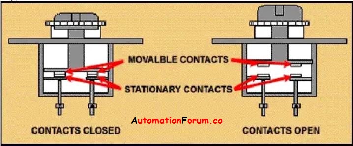
Double break contacts can simultaneously open the circuit in two places. As a result, even in a limited place, you may work with more current. Double break contacts split the connection into two sections, resulting in two sets of contacts.
The manual controller’s switch or button is physically attached to the controller and cannot be controlled remotely.
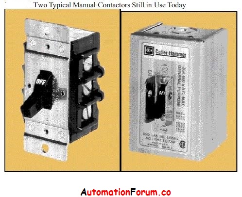
When an operator activates the manual controller, the power circuit is activated. It carries the electricity to the load once it is turned on. Manual contactors quickly replaced knife blade switches, and several varieties of these types of contactors are still used today.
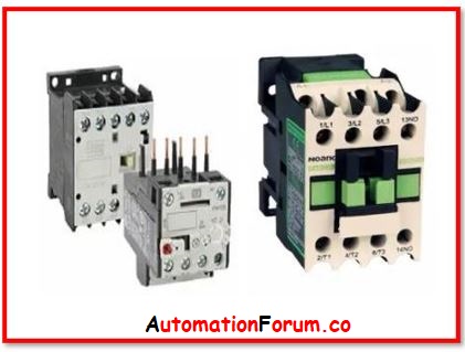
Magnetic Contactor:
The magnetic contactor is operated electromechanically and does not require human interaction. This is one of the most advanced contactors designs available, and it can be controlled remotely. As a result, it helps to reduce the dangers associated with manually operating it and placing operational people in danger. The magnetic contactor only needs a minimal amount of control current to open or close the circuit. In industrial control applications, this is the most frequent type of contactor.
Advantages of Contactor:
The following are some of the benefits of using a contactor:
- It works on a basic principle.
- It has a large carrying capacity.
- It is not difficult to construct.
- It comes in a variety of ratings.
- It has a compact design. (In particular, tiny contactors)
- It does not necessitate further cooling. Its connections do not dissipate heat very well.
- It comes with a variety of terminal connection choices. (Types include screw, spring, and busbar)
- It has the ability to endure large inrush currents. (As long as it isn’t too high)
- It consumes very little power.
- It has the ability to switch both AC and DC loads.
- It is cost-effective.
- It does not necessitate as much upkeep.
- It can work in both extremes of temperature.
- It has a wide range of applications, including motors, heaters, and illumination.
- It comes in a variety of shapes and sizes, including power, small, capacitor, modular, and bar.
- It takes only a few minutes to set up.
- It has a longer life.
- It quickly shifts the current.
- It comes with a variety of mechanical and electrical components.
Disadvantages of Contactor:
The following are some of the disadvantages of using a contactor:
- Derating can occur when the temperature is too high.
- Harmonics can have an impact on the coil. (This is especially true if the coil is of the electronic variety.)
- There is no way to communicate with it.
- Corrosion occurs when components age.
- The coils are easily combustible.
- It is not suitable for usage in harsh environments.
- It does not have a high level of ingress protection.
- This isn’t a brand-new technology. It’s been in use for almost a century.
- It does not have a circuit breaker-like protective function.
- Noise and vibration have an impact on it.
- Its contacts are easily welded.
Application of Contactors:
Capacitor Bank Switching:
Capacitor contactors are used in capacitor banks to swap capacitors based on the correction required. Capacitor switching contactors are made to regulate high transient currents when contactors are switched.
Controlling the lighting:
Large lighting installations, such as an office building or a retail store, are frequently controlled by contactors. Latching contactors, which contain two functioning coils, are used to reduce power consumption in the contactor coils. The power circuit contacts are initially closed by one coil, which is then mechanically maintained closed by the second coil, which is simultaneously powered.
Magnetic starter:
A magnetic starter is a device that supplies electricity to electric motors. It features a contactor as a key component, as well as power-cut off, under-voltage, and overload protection.
Motor Starters:
Contactors, thermal overload relays, and motor protection circuit breakers are all utilised in motor starters, whether they are Direct-on-line or Star Delta. It can even be found in our homes, in the pump starters.