- What is a Displacer Level Transmitter?
- Working Principle of Displacer Type Level Transmitter
- Step-by-Step Displacer Level Transmitter Calibration Procedure
- Purpose and Scope:
- Tools required for Calibration:
- Calibration Setup
- Safety
- Calibration procedure workbench
- What is Dry calibration?
- Difference Between Wet Calibration and Dry Calibration
- Single Liquid application
- Formula for calibration for Single Liquid application
- Example- Calibration
- Weight Calculation with Single Liquid (water) Application
- Recording calibration
- Sample calibration report
- Frequently Asked Questions on Displacer Level Transmitter Calibration Procedure Using Weight
- Conclusion Displacer Level Transmitter Calibration Procedure Using Weight
Displacer level transmitter calibration is an important procedure used in industrial process plants to ensure accurate level measurement in tanks, separators, and vessels. This guide explains the complete dry calibration procedure of a displacer type level transmitter using standard calibration weights for single liquid applications. The article includes calibration formulas, zero and span calculations, practical examples, linearity checks, troubleshooting methods, and calibration tables used by instrumentation technicians and engineers.
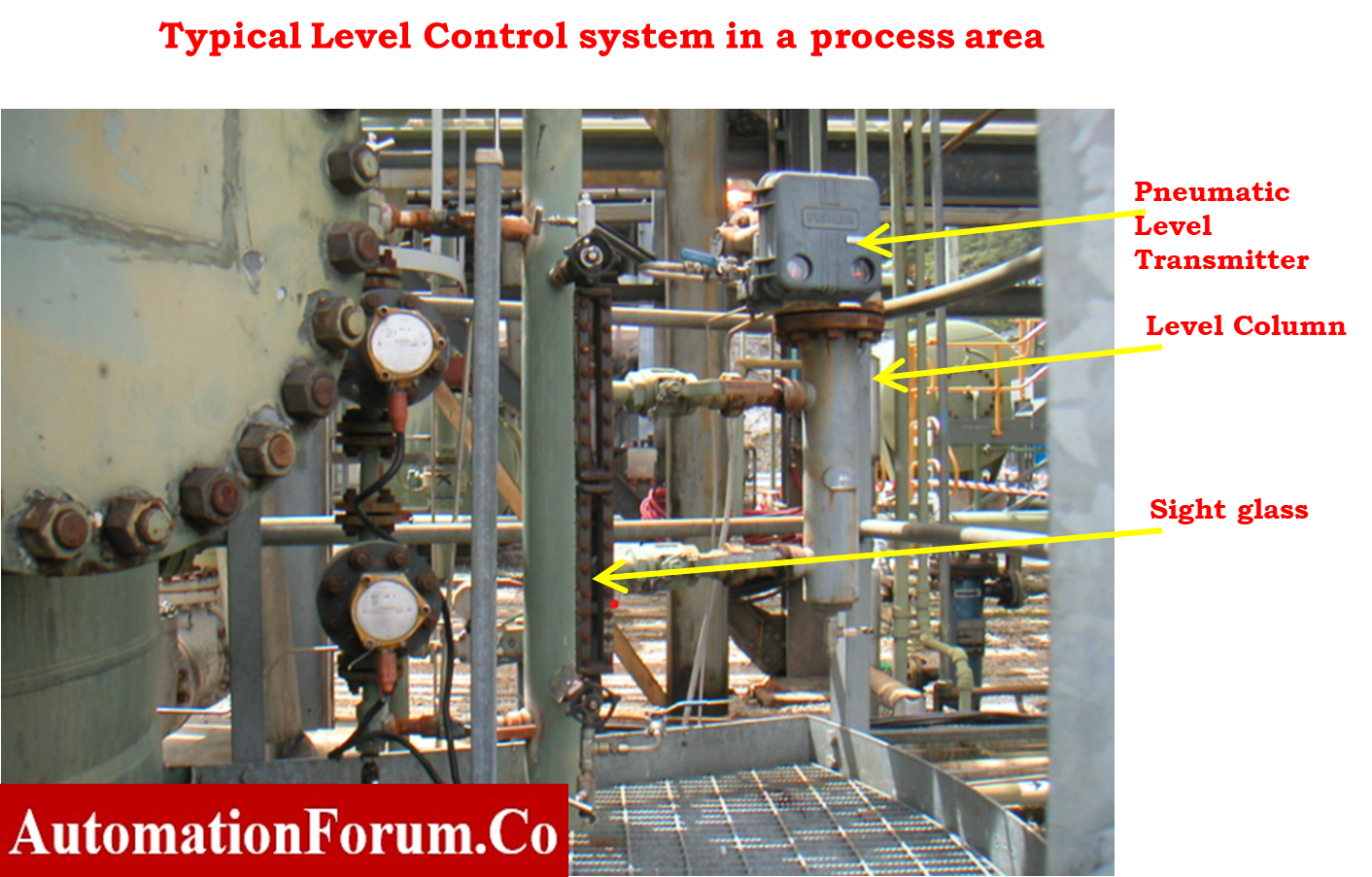
What is a Displacer Level Transmitter?
A displacer level transmitter is a buoyancy-based level measuring instrument that operates according to Archimedes principle. As the liquid level increases, the buoyancy force acting on the displacer increases, causing a reduction in the apparent weight of the displacer. This weight variation is converted into a proportional output signal such as 4–20 mA or 3–15 psi.
Displacer type level transmitters are widely used in refineries, separators, boilers, interface level applications, and high-pressure vessels because they provide stable and reliable level measurement under difficult process conditions.
Working Principle of Displacer Type Level Transmitter
The working principle of a displacer level transmitter is based on buoyancy force and Archimedes principle.
When the liquid level rises, the displacer becomes immersed in the liquid. The liquid exerts an upward buoyancy force on the displacer, reducing its apparent weight. This change in force is mechanically transferred through the torque tube assembly and converted into a pneumatic or electronic output signal.
Higher liquid level = Higher buoyancy force = Lower apparent weight of displacer.
Archimedes Principle in Displacer Level Measurement
According to Archimedes principle:
Buoyant Force = Volume of Liquid Displaced × Density of Liquid
As the liquid level increases, the buoyancy force acting on the displacer increases proportionally. This causes a reduction in the apparent weight of the displacer, which is measured by the transmitter.
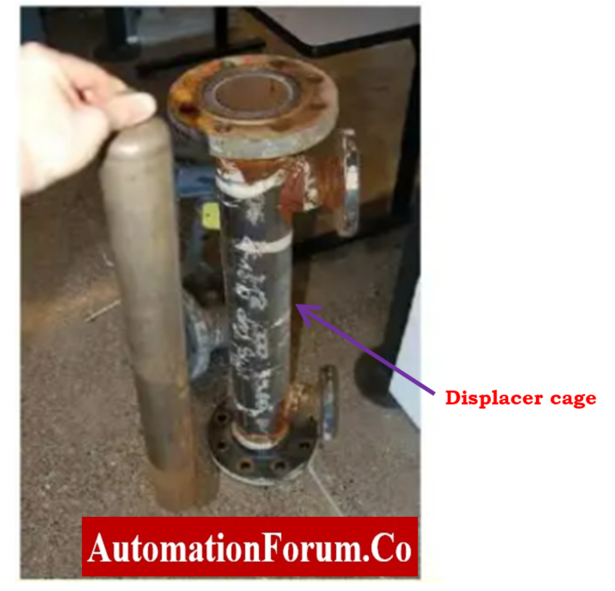
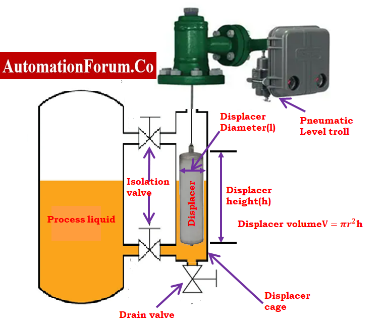
A displacer level transmitter comprises a displacer element that is hung from a hanger with a torque tube that is linked to the transmitter head. The hanger and the torque tube are both connected to the transmitter head.
The displacer element is designed and built to be heavier than the liquid in which it is being used. This ensures that the displacer element will continue to exert a downward force on the hanger even after it is completely submerged in the liquid.
Calibration of the controller and transmitter may be done in the field, where it is installed on the vessel that contains the process fluid. It is also possible to carry out the procedure in the workshop; however, another method of achieving a change in displacement force must be given. The approach for modifying the calibration may be done either by using a wet or dry method. In most cases, the dry technique is carried out in the workshop using established reference weights.
Step-by-Step Displacer Level Transmitter Calibration Procedure
Purpose and Scope:
This procedure provides calibration instructions for displacer type level transmitter/controller calibrated with standard reference weights in the workshop for single liquid application.
Tools required for Calibration:
- Necessary hand tools.
- Multimeter.
- Hart communicator of handheld configurable communicator if it is a electronic smart transmitter.
- Signal of 3 to 15 psi measuring pressure gauge for monitoring the output if it is pneumatic level controller / transmitter
- Soft Cloth for cleaning.
Calibration Setup
Safety
- For basic safety and general rules, as well as information on calibrating operations in process industries, please refer to the link provided below.
Basic Safety and General Consideration While Executing Calibration Process in process industries
- Request that the panel operator set the controller to manual mode for the control loop and MOS for the ESD loop.
- Connect the HART Communicator, and then check a few settings by consulting the data page. The tag number, PV, LRV, and URV are typical metrics.

- Keep the instrument apart from the operation.
- Take the controller/transmitter and torque tube arm out of the cage or vessel as a single unit.
Calibration procedure workbench
What is Dry calibration?
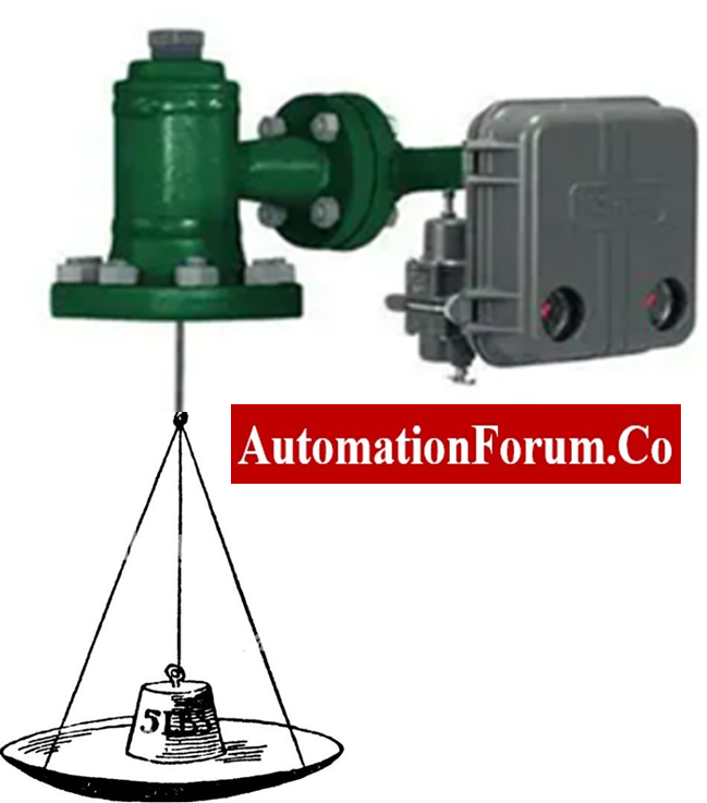
These calibration procedures require an input from a particular process variable to the sensor, simulating the process variable by suspending the appropriate weight from the end of the displacer rod.
This will allow the sensor to be calibrated without the need for the specific process variable.
Before moving on to the method for calibrating, make sure that the Controller/Transmitter and Torque Tube Arm Disassembly and the Determining the Amount of Suspended Weight procedures have both been completed.
Disassembly of the controller/transmitter as well as the torque Tube Arm
- Refer to the instruction manual for help removing the displacer from the displacer rod or the controller/transmitter and torque tube arm from the cage or vessel.

- Depending on the type of sensor, there are different ways to take off the displacer or torque tube arm and the controller or transmitter that is attached to it.
- For a caged sensor with an equalizing connection at the top, it may be best to take the whole cage out of the vessel before taking it apart.
- If the displacer needs to be taken off the displacer rod before the sensor assembly is taken out of the cage or vessel, there needs to be a way to hold the displacer so it doesn’t fall and break.
- On every displacer, the spuds or stem end pieces include holes where rods or other supports may be inserted.
- Some top-mounted sensors with long displacers can be taken off through an access hole in the head of the sensor.
- For sensors with a travel stop, the stem end piece pins will hold the displacer on the travel stop as long as the travel stop plate is in place and the sensor head is in the right place.
Determining the Amount of Suspended Weight:
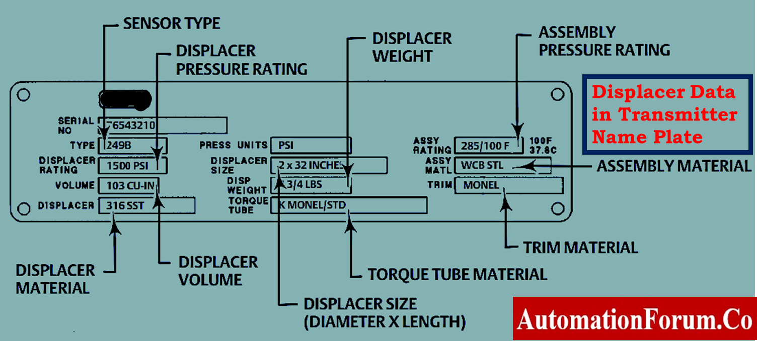
- Data has been previously recorded into the instrument memory, HART communication may be used to read the displacer’s actual volume and weight.
- Otherwise, the firm plate is marked with the displacer’s true weight, and the weight of the displacer may be determined by weighing it.
- Solve the following equation to get the total weight that has to be suspended from the displacer rod in order to simulate a certain fluid level or specific gravity condition:
- Actual volume and weight of the displacer can be read using HART communication (if data have been previously saved into the instrument memory). Otherwise the actual volume of the displacer is marked on the nameplate and displacer weight can be measured by weighing it.
Difference Between Wet Calibration and Dry Calibration
| Dry Calibration | Wet Calibration |
| Uses standard weights | Uses actual process liquid |
| Suitable for workshop calibration | Suitable for field calibration |
| Faster calibration process | More accurate process simulation |
| No process fluid required | Requires actual process liquid |
| Easy maintenance testing | Used during commissioning |
Single Liquid application
For Zero Calibration
- To do a zero calibration, attach a set of weights equal to the actual displacer weight to the torque arm to simulate the low level.
- Enter and verify the ZERO calibration by ensuring that the value shown on the display is equal to 0.0%. If not, repeat the process again until the value is very close to this one.
Zero calibration weight (LRV) = Actual weight of the displacer.
For Span Calibration
- Attach a set of weights to the torque arm that equals the apparent weight of the displacer when it is fully submerged in the calibration fluid with Specific Gravity of Calibration.
- The apparent weight (URV) is calculated as below.
Loss in weight (URV) = Weight of displacer – Weight of the displacer immersed in liquid
Displacer weight loss by liquid = Displacer Actual Volume X SG of the liquid
Displacer Actual Volume V=?r2h
r = radius of the displacer.
h = height of displacer.
Displacer Apparent Weight for span calibration = Displacer Actual Weight – (Displacer Actual Volume X SG of the liquid)
Span calibration weight (URV) = Actual weight of the displacer- Weight loss by liquid
- To do a span calibration, attach a set of weights equal to the calculated apparent weight of the displacer to the torque arm to simulate the high level.
- Enter and verify the SPAN calibration by ensuring that the value shown on the display is equal to 100%. If not, repeat the process again until the value is very close to this one.
Formula for calibration for Single Liquid application
Zero calibration weight = Actual weight of the displacer
Displacer weight loss by liquid = Displacer Actual Volume X SG of the liquid Displacer Actual Volume V=?r2hr = radius of the displacer.h = height of displacer.
Span calibration weight = Actual weight of the displacer- displacer weight loss by liquid
Example- Calibration
Weight Calculation with Single Liquid (water) Application
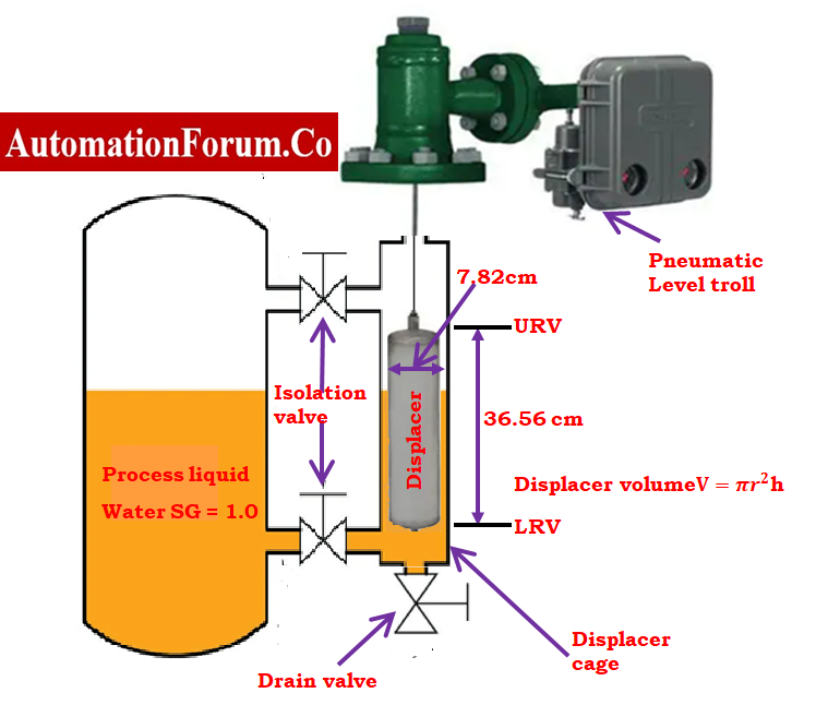
Displacer and Process Liquid Data:
- W= Displacer weight in 2500 Gram
- Displacer diameter is 7.820 Centimeter
- Length of Displacer is 36.56 centimeter
- Process liquid is Water
- Specific gravity of process liquid. (Water)= 1.0
V = Volume of displacer.
So, radius of the displacer r = 7.82/2 = 3.91centimeters
Displacer Actual Volume V=?r2h
Volume V = 3.14 × r² × h
= 3.14 × 3.91 × 3.91 × 36.56 = 1,755.049
For Zero Calibration:
- For zero percentage calibration attach a displacer or 2500 gram weight on the torque tube arm rod.
- Adjust Zero with the output signal to 4 mA / 3psi(for pneumatic level troll) .
For Span Calibration:
- For 100 percentage calibration attach the weight = Displacer weight – {Volume X Specific gravity of the liquid(water)}
= 2500 – 1755.05 X 1
= 2500 – 1755.05
=744.95 g
- Adjust Span with output signal of 20mA /15psi(for pneumatic level troll).
| Level (%) | Attached weight (gram) | Transmitter o/p (mA) | Transmitter o/p (psi) |
|---|---|---|---|
| 0 | 2500 | 4 | 3 |
| 25 | 2061 | 8 | 6 |
| 50 | 1623 | 12 | 9 |
| 75 | 1184 | 16 | 12 |
| 100 | 745 | 20 | 15 |
For linearity check each 25% step increase weight by 438.8 grams
= 1755/4
=438.8g
- Check the transmitter’s repeatability by calibrating it twice or three times.
Recording calibration
- Apply input corresponding to 0 %, 25 %, 50 %, 75 % and 100 % according to the range of Instrument in the upscale and downscale direction from the test standards.
- If the result of the output value is not within an acceptable limit, then calibration must be performed. All the output values are within acceptable limits (+/- %), then further calibration is not required.
- Record the resultant output values in the as found/ as left column of blank calibration report.
- Place calibration label on instrument once the calibration was satisfactorily done
Sample calibration report
The image that follows demonstrates that the electronic levetroll’s sample report of calibration was performed using standard test weights as the reference.
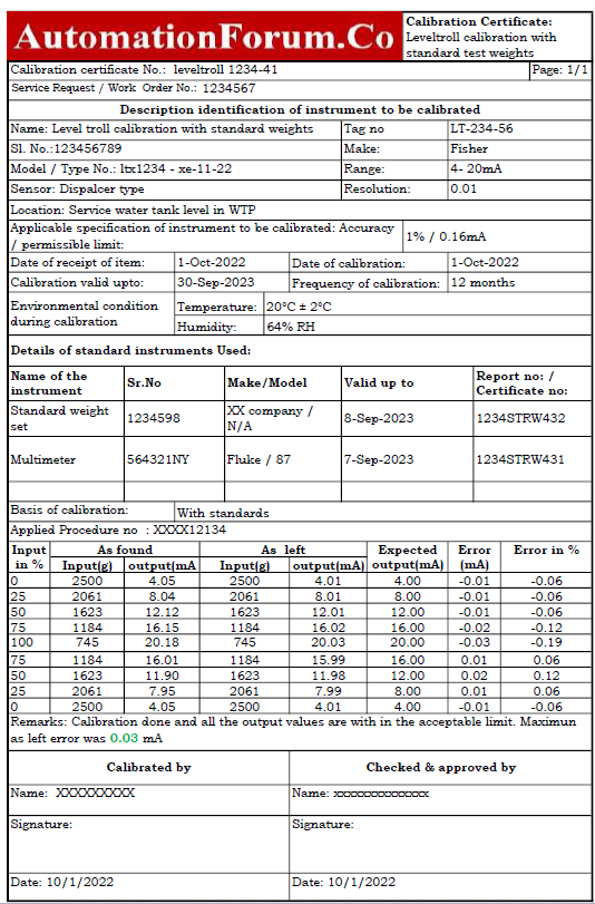
The following link provides access to a downloaded file of the excel template used in the preparation of the calibration report for Level troll.
Frequently Asked Questions on Displacer Level Transmitter Calibration Procedure Using Weight
What is dry calibration in a displacer level transmitter?
Dry calibration is a calibration method where standard reference weights are used instead of actual process liquid to simulate buoyancy force during calibration.
Why is specific gravity important in displacer calibration?
Specific gravity determines the buoyancy force acting on the displacer. Incorrect specific gravity values can cause calibration errors and inaccurate level measurement.
What is apparent weight in a displacer transmitter?
Apparent weight is the reduced weight of the displacer when immersed in liquid due to buoyancy force.
What is the difference between wet and dry calibration?
Wet calibration uses actual process liquid for calibration, while dry calibration uses standard reference weights without process liquid.
Why is linearity check important in displacer calibration?
Linearity check ensures that the transmitter output changes proportionally with level change across the entire calibration range.
Conclusion Displacer Level Transmitter Calibration Procedure Using Weight
Displacer level transmitter calibration using the dry calibration weight method is one of the most widely used procedures in industrial instrumentation. Proper zero calibration, span adjustment, specific gravity calculation, and linearity verification are essential for achieving accurate level measurement. By following the correct calibration procedure and using accurate weight calculations, technicians can ensure reliable transmitter performance in single liquid applications.