- How does NO contact work?
- How does NC contact work?
- What use do the NO and NC two contacts on a push button switch serve?
- How to determine whether a Contact is Normally Open or Closed?
- Difference Between NO and NC Contact:
- Application Difference Between NO and NC Contact
- Standard Symbols for NO and NC Contacts in Electrical Drawings
- Behavior of NO/NC Contacts Under Fault Conditions
- NO and NC Contacts in Safety Systems (Standards-Based Usage)
- Contact Materials and Load Considerations
- Single Break vs Double Break Contacts
- Latching Circuits and Memory Using NO/NC Contacts
- Using NO and NC Contacts for SCADA Feedback
- Converting NO to NC and Vice Versa
- Table: NO vs NC Contacts
- What are NO and NC in PLC Programming?
- When Should You Use NO and NC Contacts?
Logic is constructed based on the open or closed state of switches, sensors, or relays in every control circuit and automation system. Thus, understanding the NO/NC notion is essential. The phrases “normally open” (NO) and “normally closed” (NC) are used to describe the states that switches, sensors, or relay contacts are in when their coils are not stimulated. It is the core of process automation.
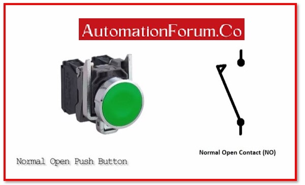
How does NO contact work?
The contact that remains open until a specific requirement is completed is known as a NO contact or a normally open contact. Consider a limit switch as an illustration. A limit switch must contain at least one NO contact. The limit switch’s NO contact stays open until the actuator is depressed. As soon as the actuator is depressed, the contact closes and begins to conduct. When it comes to proximity switches, NO contacts stay open until they detect an disrupt, and when it comes to pressure switches, the contact stays open until the predetermined pressure threshold is exceeded.
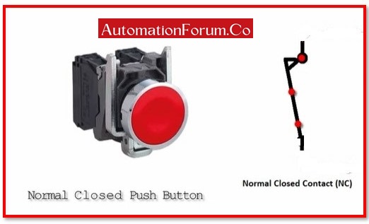
How does NC contact work?
A NC contact, also known as a normally closed contact, functions exactly the same way as a NO contact. It stays closed until a specific requirement is accomplished. In this instance, an example of limit switch action. When a limit switch’s actuator is pressed, its NC contact, which is employed in a circuit, interrupts the circuit or current flow. Similar to this, a relay’s contacts are always closed unless its coil is energised.
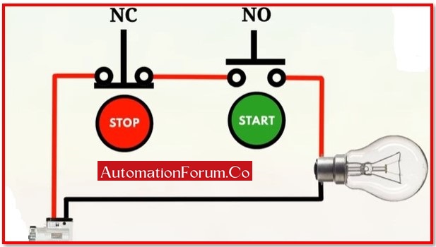
What use do the NO and NC two contacts on a push button switch serve?
When you depress the NC contact, the circuit is connected.
A maintenance relay will often be present in this circuit to maintain the circuit’s connection. In this manner, the loop is kept electrified through the maintenance relay when the push button switch is released, enabling the system to function normally. prior to the arrival of the termination signal, such as the close button or emergency stop.
Push button switches often include two contacts of NO and NC because some applications require the use of NO contacts while others require the use of NC contacts. For example, the start button requires the use of NO contacts while the stop button requires the use of NC contacts (constitute one NO contact, one NC contact). The switch differs from the lighting panel switch in that the contact returns to its initial condition as soon as the button is released. There is no defence mechanism. Circuit breakers with load and short circuit protection are used in the lighting panel switch. It will stay closed till it pulls it open if there is no malfunction.
How to determine whether a Contact is Normally Open or Closed?
The easiest way to recognise contacts is by their marking with the letters NO or NC, which are used on most switches and buttons. On the side of the component, manufacturers will occasionally place a little graphic showing the contact layout. This information is shown on a large number of contacts that are used for switches.
If the contacts are not marked, then should test them using a testing tool, such as a multimeter. In the absence of electricity and without being activated, a usually open contact will be open. When there is no power supply connected to a contact, it will be closed normally.
Difference Between NO and NC Contact:
NO and NC contacts are distinguished by the terminal:
Generally, the terminal itself can be used to distinguish between the NO and NC contacts. In general, the NO contact is at the lower end and the NC contact is at the top.
NO and NC Contact Switch Current:
The switch’s “normal” setting is when it is not being operated.
In a typically open switch, this would imply that the switch is open when it is not in use, meaning that no current can pass through it, or that the switch is off when it is not being pressed.
A typically closed switch allows current to flow through it continuously unless you decide to press the button, in which case it will turn off. A normally closed switch is closed when it is not being used.
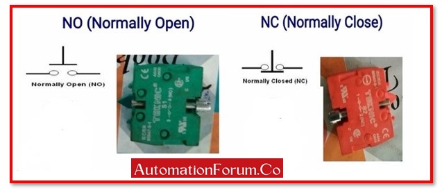
NO and NC connections can be distinguished by terminal colour:
The colour of the terminal can be used to identify some push button switches. To prevent operational errors, do this the button caps are typically constructed of various colours. Red (or pink) indicates NC contact whereas green (or blue) indicates NO contact.
Measure the NO and NC Connections:
When a resistance value exists, it is NC contact, and it is typically very small—between 0.2 – 1. It is NO contact if the resistance value is substantially high.
Application Difference Between NO and NC Contact
NO switches Application:
- Reset switch
- Toggle switch
- Footswitches
NC switches Application:
- Normally closed relays
Standard Symbols for NO and NC Contacts in Electrical Drawings
To read wiring or control diagrams, you need to know what standard symbols mean:
| Contact Type | IEC Symbol | ANSI Symbol |
| Normally Open (NO) | ─o o─ | ─[ ]─ |
| Normally Closed (NC) | ─o/ o─ | ─[/]─ |
You will often see these symbols in PLC schematics, electrical CAD designs, and wiring diagrams for panels.
Behavior of NO/NC Contacts Under Fault Conditions
To design for reliability and safety, you need to know how things fail:
- NO contacts: If a relay coil doesn’t get power, the contact stays open, which could stop the system from starting.
- NC contacts:For fail-safe designs, NC contacts are better (for example, for E-Stop). If a wire breaks or a contact fails, the circuit opens and the machine stops.
Fail-Safe Principle
NC contacts are utilized in important systems like emergency stops and safety interlocks so that any malfunction will cause a safe shutdown.
NO and NC Contacts in Safety Systems (Standards-Based Usage)
Automation safety design follows the rules set by IEC and ISO:
- If one of the redundant NC contacts in series fails, the signal path will still break.
Example: Emergency Stop Button
To meet Safety Integrity Level (SIL) or Performance Level (PL) criteria, most E-Stop buttons feature two NC contacts wired in series.
Contact Materials and Load Considerations
The right contact material depends on the type of load and the current:
| Contact Material | Application |
| Silver Alloy | High current loads (resistive) |
| Gold Plated | Low voltage/current (signal level) |
| Bifurcated | Low bounce, used in PLC input cards |
The voltage, current, and load type (resistive, inductive, or capacitive) must all match the contact values.
Single Break vs Double Break Contacts
- Single Break: Each contact has one break point. Used a lot in light-duty situations.
- Double Break: Two break points that make it better at putting out arcs. Used in safety relays and motor starters.
Application Example:
Motor contactors frequently use double break NO contacts for power lines and single break NC contacts for control interlocks.
Latching Circuits and Memory Using NO/NC Contacts
You may “remember” a pushed state in control logic by latching:
- When a stop condition is fulfilled, an NC contact can break the latch.
This is what start-stop logic in motor control is based on.
Using NO and NC Contacts for SCADA Feedback
Dry contact NO/NC outputs are frequently wired into SCADA and DCS systems for remote monitoring:
- NO contact: Sends a signal when something happens, as when a valve opens.
- NC contact:Sends a message when the device is broken or not working, like “Valve Not Closed.”
Using NO/NC contacts in feedback makes diagnostics more accurate and systems more reliable.
Converting NO to NC and Vice Versa
You can invert logic using:
- Relay logic: Energize a relay with a NO contact to control an NC output, or vice versa.
- Changeover (SPDT) Contacts: Have both NO and NC in one unit; you choose wiring as per logic.
- PLC software: Easily invert a bit or signal using a NOT logic.
Table: NO vs NC Contacts
| Feature | Normally Open (NO) | Normally Closed (NC) |
| Default State | Open (no continuity) | Closed (complete circuit) |
| State After Activation | Closed (conducts current) | Opens (interrupts current) |
| Ladder Logic Symbol | ─[ ]─ | ─[/]─ |
| Common Usage | Start push buttons, reset, call circuits | Stop buttons, emergency stop, safety relays |
| Safety Preference | Not preferred for E-Stops | Preferred in safety-critical applications |
| Color Indicator (Push Button) | Green, Blue | Red, Pink |
| Contact Testing (No Power) | Shows open on multimeter | Shows continuity on multimeter |
| Behavior if Contact Fails | Stays open may prevent system from running | Stays open safer (fail-safe) |
What are NO and NC in PLC Programming?
In PLC programming, NO (Normally Open) and NC (Normally Closed) refer to the behavior of contact instructions used in the ladder diagram language.
- A Normally Open (NO) contact instruction evaluates to TRUE when the associated variable or input signal is TRUE. It allows logic continuity when the condition is met.
- A Normally Closed (NC) contact instruction evaluates to TRUE when the associated variable is FALSE, meaning it allows logic to flow only when the condition is not active.
These contacts represent logical conditions and are commonly used to control operations based on the state of switches, sensors, or internal PLC memory bits.
When Should You Use NO and NC Contacts?
NO and NC contacts are used depending on the required system behavior:
- Use Normally Closed (NC) contacts when you want a circuit to remain active until a condition interrupts it for example, stopping a machine when an emergency stop is pressed or ensuring safety interlocks are in place.
- NC (Normally Closed): Deactivates logic when the input is TRUE (e.g., Emergency Stop, Safety Switch).
These contact types are critical for implementing reliable and safe control logic in automation systems.