Table of Contents
Introduction
- Differential Pressure Transmitter convert pressure measurements into a proportional 4-20 mA or a 1 – 5 Vdc output signal that functions as the input to a controller, recorder, indicator or similar device.
- These transmitters find application in the gas, water, and process industries that require accurate measurements over a wide range of environmental conditions.
Theory of operation
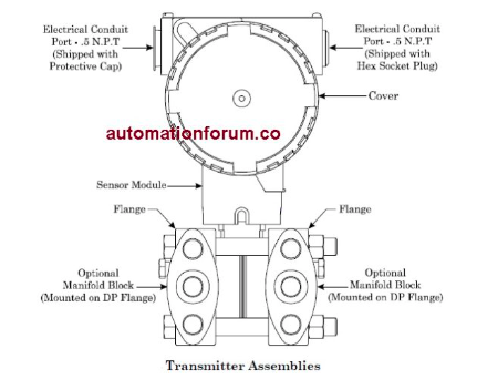
- The main assemblies of the DP transmitter are the electronics housing, sensor module and process flanges as noted in Figure. The electronics housing encloses the amplifier board and the field wiring terminals as shown in the schematic of Figure.
- The sensor module contains the pressure sensor, two sealed fluid systems, an over pressure diaphragm, and two isolation diaphragms. The flanges provide the HI and LO port connections and also function as the outer wall of the pressure input chambers
- The electronic pressure sensor located at the upper part of the sensor module is mounted on a micro diaphragm that serves as a divider between the two fluid systems.
- One fluid system corresponds to the HI pressure input, and the other to the LO pressure input.
- The isolation diaphragm of each system isolates the fluid system from the input pressure. When a differential pressure is applied across the HI and LO ports, both isolation diaphragms will compress or retract in response to the change of differential.
- The movement of these diaphragms causes similar pressure changes in each of the sealed fluid systems that are detected by the sensor.
- If the differential pressure applied to the HI-LO ports accidentally exceeds the upper limits of the transmitter, an overpressure diaphragm mechanism takes control of the situation. The action of this mechanism prevents the overpressure from reaching the sensor, thereby minimizing the risk of damage
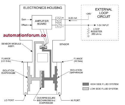
- Implanted on the sensor’s micro-machined surface are four strain gauge resistors connected in a bridge configuration. This circuit, which is powered by a constant current supply on the amplifier board, produces a mill volt output that is equal to the difference between the two pressure inputs.
- The output of the sensor circuit is wired to a high-gain, linear amplifier that converts the millivolt signals to a 4-20 mA current output. Figure shows the transmitter output wired to a typical external loop circuit. This circuit uses a 250-ohm load resistor and a 24 Vdc power source.
- The 4-20 mA amplifier current flowing through the load resistor produces a1-5 V input signal for the external device. The amplifier circuit includes a fine-gain and fine-offset potentiometer for performing minor calibration adjustments. Transmitters also include internal coarse zero and coarse span switches for more extensive range conversion.
Do you want to know more about:


 to Kg/cm² Pressure Unit Conversion Calculator")

