What is Voltmeter?
The device used to measure the electric potential difference between two points in an electric circuit is called a voltmeter. It is linked simultaneously. It typically has a high resistance such that it uses very low circuit current. Voltmeters can be used to measure sinusoidal AC voltages as well as DC voltage, however introducing a voltmeter as a measurement instrument into a circuit can interrupt its steady state operation.

What is the SI Unit of Voltmeter?
The volt is the SI unit for electrical potential.
Symbolic representation of a voltmeter:

The two terminals and the letter V in the circle are used to symbolise the voltmeter.
What is the formula of voltmeter?
where V represents the potential difference across a resistance R that a current I is passing through.
Voltmeter Working Principle:
The fundamental idea behind a voltmeter is that it needs to be connected in parallel to the device(s) being measured for voltage. A voltmeter’s high resistance value necessitates the usage of a parallel connection. Therefore, if that large resistance is linked in series, the current flow will be virtually zero, indicating that the circuit is now open.
If it is connected in parallel, the load impedance will be parallel with the high resistance of the voltmeter, giving the combination a nearly identical impedance as the load itself. Additionally, since the voltage in a parallel circuit is the same, the voltage between the voltmeter and the load is nearly the same, allowing the voltmeter to measure the voltage.
For an ideal voltmeter, the resistance should be infinite, the current drawn should be zero, and there should be no power loss in the device. However, unable to create a material with infinite resistance.

Types of Voltmeters:
We have several different types of voltmeters, most of them are based on the construction principle:
- PMMC Voltmeter (Permanent Magnet Moving Coil),
- Rectifier Type Voltmeter,
- Induction Type Voltmeter,
- Moving Iron (MI) Voltmeter,
- Electro Dynamometer Type Voltmeter and
- Electrostatic Type Voltmeter.
Depending on the output it is classified as:
- Analog Voltmeter and
- Digital Voltmeter.
Depending on the measurements it is classified as:
- DC Voltmeter and
- AC Voltmeter
PMMC Voltmeter (Permanent Magnet Moving Coil):
The PMMC Voltmeter operates on the principle that a current-carrying conductor is placed in a magnetic field and that force is applied to the conductor as a result of the current. The measurement and voltage cause a current to be induced in the PMMC instrument, and this current causes the meter’s pointer to deflect.
The DC measurement is done with the PMMC voltmeter. The instrument has a very high level of accuracy and uses low power. The instrument’s high price is its one and only drawback. By wiring the resistance in series with the PMMC voltmeter, the range of the voltmeter is increased.
Rectifier Type Voltmeter:
Rectifier Voltmeters are used to measure AC or DC. A PMMC meters that measures rectified voltage that is attached across the bridge rectifier must be connected in order to conduct DC measurements. It Can be applied frequently. Most ranges have a steady scale.
Induction Type Voltmeter:
The induction voltmeter is built similarly to the induction ammeter, with the exception that its winding is wound with a lot of turns of tiny wire. Split phase windings are created by connecting a high resistance R in series with the winding of one magnet and an inductive coil in series with the winding of the other magnet. This is done to create split phase windings because the device is connected across the lines and only carries a small amount of current (5-10mA).
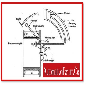
Moving Iron (MI) Voltmeter:
The term “moving iron instrument” refers to the MI voltmeter. This voltmeter is used to measure both AC and DC voltages. The deflection is directly inversely proportional to the coil voltage in this kind of voltmeter. Two categories of moving iron voltmeters available.
- Attraction-Type Moving Iron Voltmeter
- Repulsion-Type moving iron Voltmeter
Electro Dynamometer Type Voltmeter:
The voltage of both AC and DC circuits is measured using the electro-dynamometer voltmeter. The calibration in these devices is the same for both AC and DC measurements. Because electrodynamometer type voltmeters use the same calibration for both AC and DC, we can measure AC without calibrating devices if they are calibrated with DC.
Electrostatic Type Voltmeter:
The term “electrostatic voltmeter” can apply to a voltmeter used to measure high electrical potentials or to an electrostatic charge meter, also referred to as a surface DC voltmeter. There is no electrostatic charge transfer or loading of the voltage source since it can directly measure surface potential (voltage) on materials without making physical contact.
Analog Voltmeter:
The AC voltage is measured using an analogue voltmeter. Through a pointer that is fixed to a calibrated scale, it shows the reading. The torque exerted on the pointer determines its deflection. The measurement voltage has a direct relationship with the size of the developing torque.

Digital Voltmeter:
A device that can provide the output voltage without deflection by just indicating the value is the digital voltmeter. It is a particularly effective tool to measure voltage since it entirely removes parallax error and allows for high-speed reading as well as the ability to store the voltage measurement in memory for subsequent analysis. The value is measured using the same circuit configuration in general, but instead of being used to deflect the pointer, that value is supplied to the analogue to digital converter and displayed as a digital value.

AC Voltmeter:
The device known as an AC voltmeter is used to measure the AC voltage between any two points in an electric circuit. Rectifier-based AC voltmeters are those that use rectifiers as its primary component. Only DC voltages are measured by the DC voltmeter. These two procedures must be taken if you want to use it to measure AC voltages.
Step 1: Use a rectifier to change the AC voltage signal into a DC voltage signal.
Step 2: Calculate the output signal of the rectifier’s average or DC value.
By adding the rectifier circuit to the fundamental DC voltmeter, it transforms into a rectifier-based AC voltmeter.
DC Voltmeter:
An instrument called a DC voltmeter is used to determine the DC voltage between any two points on an electric circuit. The Permanent Magnet Moving Coil (PMMC) galvanometer can be used as a DC voltmeter by connecting a resistor in series with it.
Series multiplier resistance, or simply multiplier, is another name for the series resistance that is utilized in DC voltmeters. In effect, it restricts the flow of current through the voltmeter to keep the meter current from going above the full-scale deflection value. This DC voltmeter must be placed between the two places on an electrical circuit where the DC voltage is to be determined.
Voltage is displayed immediately as numbers on a digital voltmeter. Some of these meters have multiple significant numbers for the voltage values that can determine. Maximum ranges for practical laboratory voltmeters are 1000 to 3000 volts (V). The majority of voltmeters used in industry have many scales with powers of 10 increasing, such as 0-1 V, 0-10 V, 0-100 V, and 0-1000 V.

Why is the resistance on a voltmeter so high?
Since the voltmeter detects the potential difference between the two points of the circuit, it is built with a very high internal resistance. The measuring device’s current is unaffected by the voltmeter.
Low resistance causes the voltmeter to have a current flow across it, giving an inaccurate reading. The voltmeter’s high resistance prevents current from passing through it, giving the accurate measurement
Why is the voltmeter connected in parallel?
The voltmeter is built in a way that ensures a high internal resistance at all times. When it is connected in series with the circuit, the amount of current that flows as a result of the measurement voltage is reduced. As a result, interference with the voltmeter’s reading.
The circuit and the voltmeter are connected in parallel so that the voltage drop across them is constant. Combining the impedance of the element it is attached to with the high resistance of the voltmeter results in high resistance. Additionally, the system’s overall impedance is the same as the impedance that the element had. As a result, the voltmeter does not interfere with the circuit and provides the accurate measurement.
What is a voltmeter is used for?
A voltmeter is a device that measures the electrical potential difference between two locations in an electric circuit. Digital voltmeters use an analogue to digital converter to display voltage as a numerical value; analogue voltmeters move a pointer across a scale in proportion to the voltage of the circuit.
Application of Voltmeter:
The Voltmeter has several applications, such as:
- Finding the voltage of a device that stores charges, such testing the voltage of a battery, can be quite helpful.
- It can be used alone to determine whether a circuit, such as a mains outlet, is powered or not.
- Checking to see if the appliances have electricity.
- By measuring the voltage over a known resistance, we may determine the current. When you don’t have an ammeter, this is helpful.
- With a series battery, they are utilised to construct a continuity tester.
- Through the use of a voltage divider and an unknown resistance, they are used to construct an ohmmeter.
- Through monitoring the voltage across a shunt resistor, they are utilised to construct an ammeter.