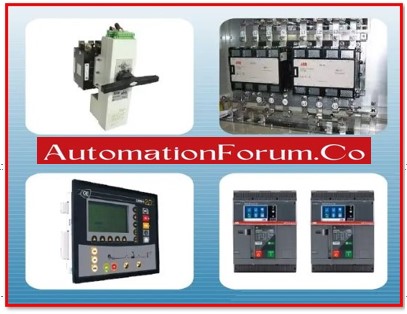
What is Changeover Switch?
A switch used to transfer the source of power supply to an electrical load is known as a changeover switch. Changeover switches are available in a variety of forms. It is divided into two types based on the operation:
1. Manual
2. Automatic
The transfer switch is also known as the automated changeover switch or the manual changeover switch made using electrical or electronic circuitry. Manual changeover switch are outdated in use.

What is Manual Changeover Switch?
The term “manual changeover switch” refers to a handle-operate switch. It is the vintage switch that was popular in the past. These days, electrical circuitry or automatic switches are used. The routes and handles on this handle- operate changeover switch are made of metal. The metallic routes of the changeover switch are set up such that they will link to one another and move the handle manually.

In general, one load and the changeover switch can be connected to two distinct power sources. The load will therefore disconnect from one source and connect to another source when the handle is moved. There are three locations available for the changeover switch’s handle:
- Source 1,
- Source 2, and
- OFF condition.
The load will be separated from both power sources if the handle is left in the off position. The load will be connected to source 1 and separated from source 2 if the handle is kept in source 1. The load will be connected to source 2 and disconnected from source 1 if the handle is held in the source 2 position.
There are three different variations of this handle-operate changeover switch.
- Type 1: It is a two-pole device that joins the phase and neutral in a single-phase power system.
- Type 2: It is a triple pole device that connects the three-phase, three-wire terminals in a three-phase electrical system.
- Type 3: This is a four-pole device that connects all three phases and the neutral in a three-phase, four-wire system.
What is Automatic Changeover Switch?
A key component of a power generation process, the automatic changeover switch (also known as the automatic transfer switch, or ATS) enables seamless and instantaneous movement of electric current between various sources and loads. The transfer switch forbids any feedback current to the load when the generator is running. Additionally, before the load is delivered to the various power sources, it makes sure that they are synced. If the mains supply is not restored, the transfer switch detects when there is an interruption. The automated transfer switch will also switch the load to the generator if there are fluctuations or a voltage drop in the mains supply below a specific level within a predetermined amount of time.
How Automatic Changeover Switch Works?

A relay that switches the battery voltage to the generator’s ignition coil initiates the start of the generator. The transfer switch disconnects the load from the mains supply and connects it to the generator supply, restoring power to the load, in a matter of seconds when the generator is delivering its maximum output. When the mains supply is back up and running, the transfer switch moves the load from the generator back to the mains supply. When the generator is unplugged, it automatically performs a cool-down process and shuts off.
Example from above Circuit Diagram:
Switch A and Switch B are placed in series in the circuit just after the bridge rectifier and adjacent to the battery supply, respectively, in order to evaluate the system’s functionality. The battery is completely charged and the main supply is available during this test. The load is a 60 W bulb, and the kick-starter is a 12 Volt motor. Another aspect of the main supply is employed during the test in place of the generator supply. The circuit’s operation comprised the following steps:
- Switch A is open (OFF), simulating a public supply interruption.
- Switch A closed (ON) simulates the availability of public supplies.
- Switch B being open (OFF) represents a bad battery, a lack of batteries, or a malfunctioning generator.
- Battery availability is simulated when Switch B is closed (ON).
- When the motor is ON, it revolves for around 4 seconds.
- Light ON (60W bulb lights).
Advantages of Changeover switch:
The advantages apply to the automated changeover switch:
a) It lessens equipment damage because it has its own monitoring and surge protection system, and because switching is automatic, there is no room for human error.
b) Because of its quick reaction times, it upholds a high standard of service.
c) Because of its quick response to a power interruption, it reduces the amount of time required for changeovers.
d) In addition, the load for which the changeover unit will be employed will affect the size and capacity of the unit.


