Valve guiding is necessary for proper alignment with the seat ring and efficient control of the process fluid. The common method used are listed below:
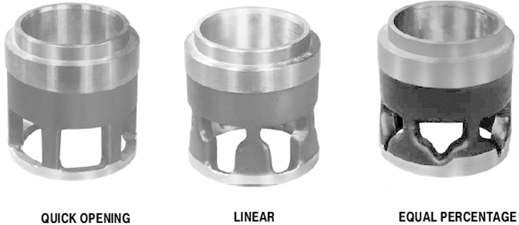
Cage guiding:
The cage allows positive alignment and control of the plug. The outside diameter of the valve plug is close to the inside wall surface of the cylindrical cage throughout the travel range. This ensures correct valve plug/seat ring alignment when the valve closes. The cage guiding can provide a stable control to high drops of pressure.
In addition, the guide of the cage reduces the vibration and the mechanical noise.
The most common maintenance problem with cage guiding is galling and sticking due to the close metal-to-metal contact between cage and plug.
Top Guiding:

Valve guide is aligned by a single guide bushing in the bonnet or valve body or by packing arrangements. Top guide valves may be used for tight shutoff applications. Because these valves are unbalanced, They can require more force from the actuators.
Stem Guiding:

The valve plug is aligned with the seat ring by a guide bushing in the bonnet that acts on the valve plug stem. Pressure energized PTFE seal is used.
Top-and-Bottom Guiding:

Valve plug is aligned by guide bushings in the bonnet and bottom flange. Dynamic force on the plug tends to
be balanced as flow tends to open one port and close the other.
Bodies normally have higher capacity than single-ported valves of the same line size.