- What are PLC Timers and Counters?
- Why timers and counters are used in PLC?
- What is a PLC Timer?
- Timer instructions
- Types of PLC Timers
- What is a PLC counter?
- Practical Applications in Process Industries
- Common Troubleshooting Issues and Solutions
- Best Practices in using Timers and Counters
- Relevant Standards
What are PLC Timers and Counters?
- Timers: Provide time-based control functions in PLC logic. They generate time delays or measure elapsed time before an event occurs.
- Counters: Count the number of events (pulses, signals, objects) and trigger actions when a preset count is reached.
Timers and counters are software instructions but mimic the behavior of physical timing relays and counters, with the advantage of being programmable, accurate, and reusable across multiple applications.
Why timers and counters are used in PLC?
A PLC is a specialized computer that is used to control and operation of manufacturing process or machinery. It is not possible to control complex systems by using certain logic and it is because we can’t use sensors to check all the conditions. So during these conditions, we use events to determine the condition of the system. Mostly a PLC would use certain events such as PLC scanning which indicates that the PLC has just been turned on. The timer is used to indicate that the input is turned ON/OFF or to create a delay. Counters are used to count the set of events that have occurred and the latch or unlatch is used to lock something ON or to turn it off.
There is memory space in the PLC to store instructions and it would also do the functions such as timing, counting, arithmetic, data handling, and sequencing. The timers and counters are used in a PLC for its continuous operation so they are inevitable in a PLC. The timer would time up to the value set by the user and the counter will count up to the value set by the user. The timer and counter both are of 16 bits, the timers and counters are the fundamental PLC instructions and it is common to all PLCs. Both the timer and counter would function as output instructions in a PLC program.
- What are the different operating modes in PLC?
- What are the types of programming languages used in PLC?
- PLC communications
- What are the components of a PLC?
- How to do the PLC maintenance and how to select a PLC?
- How to install a PLC and how to do the PLC wiring?
- How to do the commissioning and testing of a PLC?
What is a PLC Timer?

Need for timer in a PLC
In many of the PLC control tasks, there is a need to control the time an example of this will be using a PLC to control a motor. The motor would require to be controlled to operate for a certain interval, and that’s why PLCs have timers and the timers are built-in devices in a PLC. By using the internal CPU clock the timer would count the time. Different PLC timers are programmed in different ways, so we can consider a timer to act as a relay with coils, which would open or close when it is energized according to the pre-set time.
Timer instructions
The timer instructions are the output instructions which is used to time the intervals for which the rung conditions are true or false. The timer accuracy will be depended upon the microprocessor which is being used. The timer instruction is composed of two values and they are
- Accumulated value – This is a current number of time-based intervals that have been counted from the moment when the timer is energized.
- Preset value – This value is set by the programmer, if the preset value is less than or equal to the accumulated value then a status bit is set and this bit is to control an output device.
Each timer is composed of two status bit
- Timer enable-bit – This bit will be set if the rung condition to the left of the timer instruction is true and when this bit is set then the accumulated value will be incremented on each time base interval till it reaches the preset value.
- Done bit – This bit will be set if the preset value and the accumulated value are equal and it will be reset if the rung condition is false.
Timer working
The timer will be activated if the execution condition is started and it will be reset if the execution condition stops or goes OFF. If the execution condition keeps ongoing or if it is long enough for the timer to time down to zero. Then the completion flag will be turned ON and it will remain ON till the execution condition is completed or turn off.
The address of the timer is unique in the PLC memory, the timer instruction is one element and the timer element is composed of 16-bits. The word zero will cover the status bits and it has three state bits such as EN, TT, and DN. The word one is for the preset value and the word two is for the accumulated value
Types of PLC Timers
We can see different types of timers in a PLC
ON Delay Timer (TON)
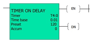
This type of timer can be seen in small PLC’s and this timer would be on after a particular time delay. This is widely used for PLC programming we can also create other timer functions by using an on-delay timer. So this timer would delay the turning ON time in a system. This type of timer would count the time base interval if the instruction is true. So if the rung condition becomes true then the on delay timer instructions will start to count the time base intervals. So if the rung conditions stay true then the timer would adjust its accumulated value during each evaluation till it reaches the preset value. So when the rung condition becomes false then the accumulated value is reset. The three timer bits EN, TT, and DN can be used as rung conditions.

OFF Delay Timer (TOF)

This is the exact opposite of the on delay timer, this timer would delays the turning off. So these timers are on for a fixed period of time before turning off. The output will be turned off after a delay, so when this timer is turned on then the output is also turned on. So if the output needs to be turned off then it needs to be turned on in the beginning. So this timer won’t be activated before we turn the input off again, so if we do that the timer will start the count after the delay and the output will be turned off.

Pulse timer
This timer is not used widely in a PLC it can be very helpful for some PLC operations. The pulse timer is used to generate the pulse and it will be of a specific length. The pulse timer can be activated by turning on the input and when it is turned on then the timer would start counting the time. So basically a pulse timer can switch on or off for a fixed period of time.
Retentive Timer (RTO)
- Function: Accumulates time across multiple input signals until reset.
- Application: Machine cycle monitoring, total run hours calculation.
- Difference from TON/TOF: Does not reset when the input goes OFF, unless a RESET block is used.
What is a PLC counter?
The counters are needed in a PLC to detect the numbers and events, mostly the controller needs to operate with the counters. The counters are used to eliminate the requirement of relays to represent the events that have occurred. The counters are used to index, increment, or decrement the values. The counter would count from zero to the predetermined value and it is the preset value. Mostly the counters are used in PLC to count items an example of this will be counting the cans which go into a box on an assembly line. So the counters are really important, if a box is filled then it needs to be moved so that another one can be filled. So basically a PLC counter is a function block that would count up or down till it reaches a limit and when the output is set then the limit is reached.
The counters can help to log to SCADA systems, they would count the number of times the event has happened or it would set the alarm when the event happens for a certain amount of time. The counters consist of variables and it is used to store the numbers in the PLC. All the counter would store a minimum of two numbers and they would be counter limit and current counter value. These two numbers will be saved as word or integer data types.
Up Counter (CTU)

This counter is used to count up, the Up counter will count from zero up to the pre-set value and events will be added till the number reaches the preset value. So when the counter reaches the set value then its contacts would change state. This counter will increment the accumulated value at each false to true transition and it would retain the transition when the instruction goes false or in the case of power cycles. This counter is capable to count the false to true transition and during this type of transition, the accumulated value is incremented by one count.
Down Counter (CTD)

This is another step that is widely used in a PLC, this type of counter will count down. By using a down counter we can determine how many counts are remaining before the limit is reached. By using a down counter we can count down from a certain number till it reaches zero. Instead of a reset the down counted has a pin and it is called load and it will load a value to the current counter value and it is because to count down to zero an initial value is needed. Each pulse on the count input will decrease the current counter value by one. If the CV is less than or equal to zero then the output is set. The load input would add the value of the counter limit to CV.
Up/Down Counter (CTUD)

This type of counter can count in both ways and this could be useful for certain PLC functions. We can count a number both up and down and also can set an upper or lower limit. Each pulse in the count input (CU) will increase the current counter value by one. Each pulse on the count input (CD) will decrement the current counter by one. If the CV is greater than or equal to the counter limit (PV) then the output is set. If the CV is less than or equal to zero the output (QD) is set. A pulse on the reset input (R) will reset the value of the CV to zero. The counter limit value will be added to CV by the load input pulse.
Practical Applications in Process Industries
- Process Delay: Using TON to delay opening of a valve until system pressure stabilizes.
- Purge Timing: Using TOF to run purge fans after shutdown.
- Machine Safety: Retentive timers track cumulative run-time for preventive maintenance.
- Batch Counting: CTU for packaging line bottle counts.
- Inventory Tracking: CTD to decrement stock in automated storage systems.
- Two-Way Movement: CTUD for crane movement or lift position control.
Common Troubleshooting Issues and Solutions
| Issue | Possible Cause | Solution |
|---|---|---|
| Timer not starting | Wrong input condition | Check ladder logic enable input |
| Timer resets unexpectedly | Used TON instead of RTO | Use Retentive Timer for cumulative logic |
| Counter not counting | Signal not detected | Check sensor wiring and debounce filter |
| Counter overflows | Exceeded max count range | Use double-word counters (32-bit) |
| TOF output never turns OFF | Wrong preset value | Verify preset and reset conditions |
Best Practices in using Timers and Counters
- Use TON for delays, TOF for post-action, and RTO for cumulative time.
- Avoid very small timer values (<50 ms) to prevent scan-time issues.
- Implement debounce logic for counters to avoid false counts from noisy signals.
- For large counts, use 32-bit counters or memory registers.
- Always include a RESET logic for counters and RTO timers.
- Document timer/counter usage with clear tag names (e.g.,
Motor_Start_Delay_TON).
Relevant Standards
- IEC 61131-3: Defines standard PLC programming languages and function blocks.
- ISA-88 / ISA-95: Batch and enterprise integration standards where counters and timers play a role.
- OEM Standards: Siemens, Rockwell (Allen-Bradley), Schneider, and Omron follow IEC blocks with slight naming differences.