A PLC is a digitally operating electronic apparatus and it has a program memory to store the instructions. These instructions are for certain functions in order to do certain functions such as logic, sequencing, arithmetic, etc. So basically a PLC is an industrial computer that would monitor inputs and depending upon their state it would make decisions based on its program or logic to control its output to automate machine or process.
Major components of PLC
- Power supply
- Processor module – CPU, memory
- Communication interface
- I/O modules
- O/P modules
- Software
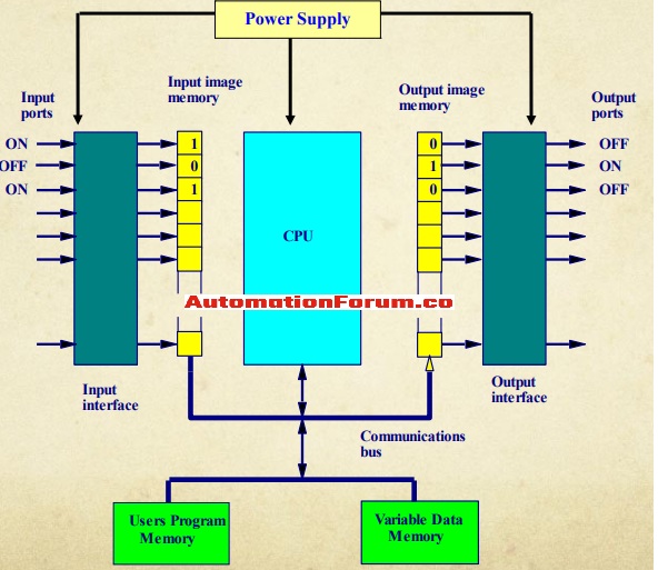
POWER SUPPLY
The power supply is required to run the primary PLC components, most of the PLC controller would work either at 24 VDC or 240 VAC, certain PLC controllers would have electrical supply as a separate module. The system power supply not only provides the power it also monitor and regulate the supplied voltages and warns the CPU if there is anything wrong. The power supply would provide a well-regulated power and protection for other system components. Most of the industrial facilities would have fluctuations in line voltage and frequency and because of this, the PLC power supply must be able to handle a 10 to 15 % variation in the line voltage condition.
CPU
The central processing unit is the major part of the PLC and it performs the tasks which are needed to complete the functions of the PLC. The CPU would have a program that would tell the PLC how to execute the control instructions. The CPU controls and processes all the operations within the PLC and because of this, it is called the PLC brain. The CPU would communicate with other PLCs, programming devices, and I/O devices. The CPU is a microprocessor-based circuitry, the CPU consist of an arithmetic logic unit, program memory, process image memory, internal timers, and counters.
Arithmetic logic unit – The major function of an ALU is to do the arithmetic and logic operations with the data transmitted. The accumulator is a part of the ALU and this would store both the data to be processed as well as the result of an operation. The instruction register stores the command from the program memory until it is decoded and executed. A command would have an operation part and an address part. The operation part would indicate which logic operation must be carried out. The address part would define the operands with which a logic operation is to be executed. The program counter would have the address of the next command to be processed. The counter unit would regulate and control the entire logic sequence of the operation which is needed for the execution of the command.
Functions of the CPU
- It receives inputs from various sensing device and switches
- It executes the user program
- It is capable to make various decisions in order to control the operation of the equipment or the process
- It can do many arithmetic and data manipulation functions
- It is capable to deliver the output to various load control devices such as relay coils and solenoids
INPUT MODULE
The input devices are pushbuttons, sensors, potentiometers, pressure switches. The input module would change the high voltages to low-level voltages which the CPU can use for processing. The input module is capable to process both the analog input and the digital input, mostly digital inputs are used in industries. The analog input module would convert analog signals from analog devices such as temperature sensors, pressure sensors. The analog signals from these devices would be converted to digital with the help of an ADC. Analog signal would be varying voltage and it would be in the range of 0-12V or current in the range of 5-20ma and these values will be converted into integer values.
The input and output modules would allow the PLC to check and control a process, the input section is composed of I/O rack and individual I/O modules. The input interface module would receive a signal from the machine or process device and converts it into signals which can be used by the controller. The input interface would enable details regarding the process that is to be communicated to the CPU. In the input section, the status signals are filtered to remove noise. Many I/O modules can be inserted into the rack of the PLC, and this section provides a connection to the machine and the process. The input to PLCs is discreet signals from the input device. The I/O modules can be located near the I/O devices with the help of remote I/O and by doing this the wiring connection can be reduced.
Functions of the input module
- It can sense when the signal is received from a sensor
- It would also convert the signal to the proper voltage for the PLC
- It would also isolate the PLC from the fluctuations in the input signals voltage or current
- It would also send a signal to the processor indicating which sensor originated the signal.
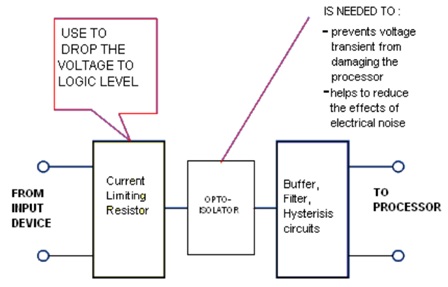
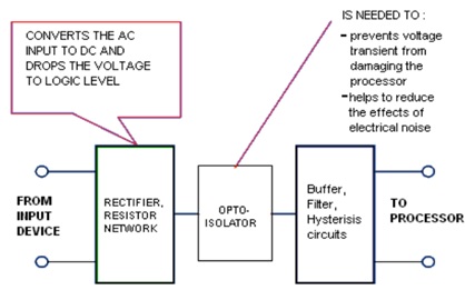
The input module would respond to the input signal in this manner
- The voltage transients are reduced or removed by the input filtering and by this there won’t be any false data
- The optical isolation will protect the backplane circuits and module logic circuits from the damage which could happen from the electrical transients.
Types of I/O circuits
Discreet I/P
This type of circuit can sense the status of limit switches, pushbuttons, and other discreet sensors. It will also do the noise suppression and by that, it will prevent false indication of Inputs.
General purpose outputs
Mostly this is a low voltage and low current and it is used to indicate lights and other non-inductive loads
Pilot duty outputs
This type of output is mostly used to drive the high current electromagnetic loads such as valves, motor starter, etc. it can withstand high inrush currents and this load is highly inductive.
Analog I/O
This type of circuits can sense or drive the analog signals, the analog inputs comes from devices such as strain gauges, thermocouples, or pressure sensors, and it will provide a signal voltage or current which is derived from the process variable. The standard analog I/P signal is 4-20 ma, 0-10v
DC I/P module
AC I/P module
OUTPUT MODULE
The output device is composed of controller coils, solenoid coils, lamps, etc. The output module would amplify the low-level logical signal which is generated by the CPU and then it would transmit these modified signals to the final control elements to operate the output devices. This module would convert the controller signals to external signals which can be used to control the machine or process. The output interface would allow the CPU to communicate operating signals to the processing device under its control. The output module is capable to convert the signals from the CPU into analog or digital values which can be used to control different output devices.
Memory
Memory is the part of the PLC which stores data, programs, and information. The process of adding new information into memory is called writing, and the process of retrieving information from a memory location is called reading. The major types of memory which are used in the PLC are read-only memory and random access memory. We can only read Rom location but it can’t be written, the ROM would have programs and data which should not be edited like the operating programs. The RAM location can be used to do the reading and writing and by this, we can edit or change the information which is stored in the RAM.
System buses
This is the internal path through which the digital signals flow within the PLC. Mostly the system would have four buses, the data bus is to send data between different elements, the address bus is to send the address of the locations in order to access the stored data, the control bus is for the internal control, and the system bus is for the communication between the I/O ports and I/O units.
SOFTWARE
The PLC has two parts the operating system and the user program. The operating system of the PLC provides proper support from the starting of the project to the creation of the user program. The major window would have all the functions which are needed to set up a project, and also to configure the hardware, write, and set up a program. During the processing of the PLC program, the CPU would scan and execute the main program cyclically. A program scan cycle consists of sequential operations which include input scan, program scan, and output scan. In the input and output scan of the PLC, the CPU updates the process image of the input and output. So after the completion of each scan cycle, the CPU would return to the next cycle and repeats the cycle and the required to scan one program is scan cycle time.