In this article, we will discuss the fluids in the sugar industry and cogeneration plants.
The various fluid types are cane juice, imbibition water, syrup, massecuite, molasses, return condensate, boiler feedwater, main steam, exhaust steam, and so on…
The selection of the flow meter is a very important aspect because there are a variety of fluids available in the process industry.
How are the flow meters classified?
The flow meters are classified as.
- Mechanical type: Orifice plate, Mass flow meter, Flow nozzle.
- Electrical type: Electromagnetic flowmeter.
- Inferential type: Rotameter
How are the flow meters selected?
Depending upon the viscosity and conductivity of the Fluid the Flow Meters have been selected, they are.
- For lower viscosity and conductivity
- Orifice meter
- Mass flow meter
- Rotameter
2. For higher viscosity and conductivity
Magnetic flowmeter
The table below shows the selection of flow meters based on fluid type.
| Sl. NO: | Fluid Type | Flowmeter |
| 1 | Boiler Feedwater | Orifice Meter |
| 2 | Main Steam | |
| 3 | Exhaust Steam | |
| 4 | Imbibition Water | Magnetic Flowmeter |
| 5 | Syrup | |
| 6 | Massecuite | |
| 7 | Molasses | |
| 8 | Return Condensate | |
| 9 | Raw Juice | Mass Flowmeter |
| 10 | Air Flow | Rotameter |
ORIFICE METER:
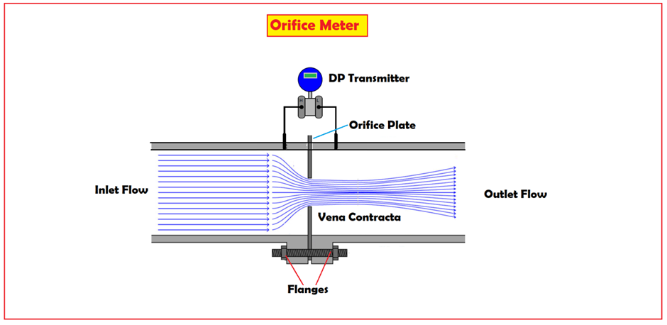
Principle of Orifice meter:
The orifice plate installed in the pipeline causes the variation in flow velocity and a corresponding decrease in pressure.
The fluid flow in the orifice shows an effective decrease in cross-section beyond the orifice plate, with a maximum velocity and minimum pressure drop at the vena-contract.
The orifice works on two principles:
- Continuity equation:
According to this equation as the flow is inversely proportional to the fluid velocity.
Q=A1*V1=A2*V2 = Constant
- Bernoulli’s equation:
This equation provides a basis for correlating the increase in velocity head with the decrease in pressure head.

Where
P1 & P2 are pressures at sections 1 & 2
V1 & V2 are velocities at sections 1 & 2
Z1 & Z2 are raising at sections 1 & 2
The velocity V2 at restriction section 2 increases, hence kinetic energy is higher at section 2
Thus any change in the flow rate through the restriction can be measured in terms of differential pressure across it.
Working of Orifice meter:
- The orifice plate whose flow rate is to be measured is fixed in a fluid line with a pair of flanges.
- The plate creates an obstruction to the fluid flow by providing an opening in the form of an orifice.
- The cross-sectional area “A” of the pipe is larger than the cross-sectional area of “B” of the pipe.
- At a distance away from the orifice the flow lines run parallel and are widely spaced as fluid approaches the orifice the flow is now slowly converged at the upstream or inlet side of the orifice and is then diverged at the downstream or outlet side of the orifice.
- The minimum flow area exists near the orifice due to the converging and diverging of the fluid flow.
- The static pressure at the upstream side of the orifice is greater than the vena contracta.
- The position of vena contracta depends upon the rate of fluid flow.
What does vena contracta mean in an orifice?
Vena contracta: It is the region in the fluid flow near the orifice where the diameter of the stream is less, and the velocity of fluid flow is maximum.
What is the beta ratio in the orifice?
Beta ratio: it is defined as the ratio of the orifice bore to the internal pipe diameters.
The beta ratio is given by ? = d/D
Where
d= diameter of restriction.
D = diameter of the pipe.
It consists of an orifice plate as a primary element and a liquid column manometer or flow transmitter as a secondary element to measure the flow rate of the fluid.
What are the different types of orifice plates?

There are three different types of orifices
- Concentric:
- This type of orifice plate is used for the measurement of water, steam, and gas service.
- The beta ratio varies for a variety of fluids.
For liquid, the beta ratio falls between 0.15 to 0.75.
For gasses and steam, the beta ratio falls between 0.20 to 0.70.
For best results, the beta ratio must lie between values of 0.4 and 0.6.
- Eccentric:
- The eccentric orifice plate has an eccentric hole.
- It is used for measuring the fluid containing solid particles, oil containing water, and wet steam.
- Here the flange tap in the eccentric type orifice plates must be 90º or 180º to the opening by using either vena contracta or flange taps.
- Eccentric orifices must have the bore offset from the center to reduce the problems in services of fluids containing solid materials.
- Segmental:
- This orifice plate has a hole in the form segment of a circle. This type of plate is used to measure slurry and colloidal fluids.
- The tap location should be 180º from the center of tangency for higher accuracy.
Advantages:
- Simple construction and inexpensive.
- Easily fitted between flanges.
- They have no moving parts.
- Large range of sizes.
- Suitable for all types of fluids.
- Can be installed at any angle.
Disadvantages:
- Gets easily clogged due to impurities in gas or unclear fluids.
- Downstream pressures cannot be recovered like in the venturi meter.
- Low discharge coefficient
- The density, pressure & viscosity fluctuations affect the accuracy by 1%
ELECTROMAGNETIC FLOWMETER

Working principle of Electromagnetic Flowmeter
The operating principle of the magnetic flow meter is based on faraday’s law of magnetic induction
Faraday’s law of induction states that “As the conductor moves at right angles through a magnetic field “B”. The voltage produced across that conductor is directly proportional to the voltage “V” of that conductor.”
In a magnetic flow meter, the electrically conductive fluid works as a conductor.
According to faraday’s law when a conductive fluid flows through a magnetic field it generates voltage. And the voltage generation is directly proportional to fluid flow. If fluid flow is more the voltage (EMF) is generated is also more.
E= B*L*V
The volume flow rate is given by
Q = V* (?*D2/4)
Where
B — Magnetic flux density
L — The length of the conductor
V — The velocity of conductive fluid
D — Pipe diameter
Q — Volume flow rate
Working of magnetic flow meter
- Let us consider a magnetic flow meter is fixed in a pipeline with a pair of flanges whose volume of the fluid is being measured.
- The fluid that is to be measured using the electromagnetic flowmeter must be electrically conductive.
- The fluid flowing through the flow meter can be visualized as a continuous movement.
- A conductive fluid contains positive and negative charged particles and is evenly distributed in the fluid.
- The flow of these charged particles produces an electromotive force through the conductive fluid.
- When a current is applied to an electromagnetic coil they generate a constant magnetic field across the cross-sectional area of the flow tube.
- This magnetic field applies a force to the charged particles and as a result, the positive and negative charged particles in the fluid get separated and are collected on the opposite side of the flow tube.
- Now electrical voltage is formed this electrical voltage is picked up by the electrodes and is sent to a transmitter which is either mounted on the flow meter or connected remotely.
- This induced voltage is proportional to the velocity of the fluid in the pipe.
- The flow volume can be calculated easily by knowing the fluid velocity and the cross-section area of the pipe.
Advantages:
- No obstruction in the flow path,
- Very little or no pressure drop
- Can measure slurries and greasy materials.
- Can handle small as well as large flow rates.
- The parameters like viscosity, density, and the temperature don’t affect the flow measurement
- High response
- Low maintenance because of no moving parts.
Dis-advantages:
- Small size meters are bulky and expensive.
- The fluid flow pipe must run full, so there is a need of regulating valves at the upstream side of the meter.
- These meters can be used only for fluids that have reasonable electrical conduct.
MASS FLOWMETER

Principle of Mass Flowmeter:
The mass flow meter works on the principle of the Coriolis Effect.
“For a given liquid or gas that flows through a tube that is being vibrated by a small actuator”.
By this Coriolis acceleration is introduced artificially into the flowing stream, which develops a measurable twisting force on the tube resulting in a phase shift.
Working of Mass Flowmeter:
- A tube is located inside the flow meter.
- If there is no flow inside the tube then an exciter makes the tube oscillate constantly and uniformly.
- The highly sensitive sensors precisely record the tube oscillation that is placed at both inlet and outlet sides of the tube.
- As the fluid starts flowing through the tube an additional twisting is imposed on oscillation as a result of liquid inertia.
- Due to the Coriolis Effect, the upstream and downstream sections of the tube oscillate in different directions at the same time.
- The highly sensitive sensors pick up this change in oscillation in terms of time and space known as phase shift and are a measure of the direct flow of fluid through the line.
- The fluid velocity is proportional to the greater deflection of the oscillating tube.
- This Coriolis mass flow meter can also be used to determine the density of the flowing fluid and how often the measuring tube moves back and forth in one second.
- The tube oscillation depends upon the viscosity of the flowing fluid it means the tube filled with a fluid having lower viscosity like water or cane juice oscillates more frequently than the tube filled with higher viscosity fluid like honey or syrup.
- The oscillating frequencies are the direct measure of fluid density and flow and are determined simultaneously and independently during the tube oscillations.
- Using Coriolis mass flow meter the process parameters like mass flow, volumetric flow density, and temperature can be measured simultaneously.
Advantages:
- Capable of measuring difficult handling fluids
- Independent of density changes
- No routine maintenance required
- High accuracy
Dis-advantages:
- Not available for large pipes (up to 150 mm only)
- Expensive compared to other flow meters.
- Difficulty in measuring low-pressure gasses.
VARIABLE AREA FLOW METER (ROTAMETER)

Principle of Rotameter
The rotameter works on the principle of up-thrust force exerted by fluid and force by gravity. The pressure difference across an annular orifice is directly proportional to the square of the flow rate.
Working of Rotameter
- Rotameter consists of a hollow transparent and tapered glass tube placed vertically in such a way that a larger end is at the top.
- The glass tube is made up of borosilicate which is highly resistant to chemical actions and thermal shocks.
- The rotameter is mounted vertically and the flow is permitted in the upward direction.
- The float is made up of steel or lead.
- The float installed in the rotameter must be heavier than the fluid flow and its density must be greater than the working fluid.
- The variable area is set between float and internal surface.
- For the given flow rate the flow will assume a certain position at equilibrium.
- The float is allowed to travel on a vertical axis inside the glass tube.
- The fluid flow rate is determined by the position of the float inside the meter.
Advantages
- It has a low-pressure drop
- It can handle any corrosive fluid
- Its accuracy is high at lower flow rates.
- Provides linear scale.
Dis-advantages.
- It must be installed in a vertical position only.
- Expensive for high temperature and pressure.
- It cannot be used for liquid having a large percentage of solid.
- Uncertainty of measurement.