Table of Contents
This guide explains how to perform a reliable functional test on a solenoid valve using instrument air. The procedure covers the recommended test setup the step by step operation what to record and basic troubleshooting. See the attached image for a typical test layout showing the Air Filter Regulator AFR the solenoid valve the test pressure gauge and the ball valve.
Equipment and preparation
- Air Filter Regulator AFR with pressure gauge
- Solenoid valve under test Check the nameplate or datasheet for coil voltage and current for example 24 V DC coil
- Test pressure gauge with a suitable range for the system
- Ball valve to isolate the outlet during and after the test
- Wiring and a safe 24 V DC supply for the coil with proper terminals and switches
- Personal protective equipment and lockout tagout tools
Before starting confirm the valve model and coil rating on the nameplate or datasheet verify port configuration and inspect tubing and fittings for damage or leaks.
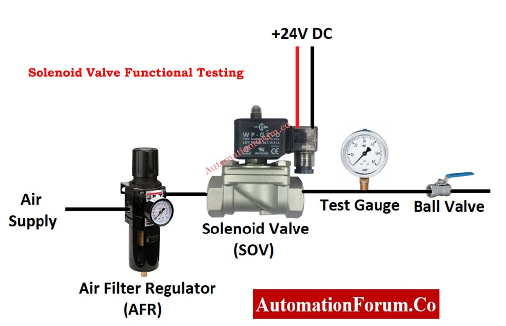
Typical test setup see attached image
- Connect the plant or bench air supply to the AFR inlet.
- Set the AFR to the required test pressure.
- Run the AFR outlet to the solenoid valve inlet.
- Fit the test pressure gauge at the solenoid valve outlet.
- Place a ball valve downstream of the gauge to allow isolation.
- Connect the solenoid coil to the 24 V DC supply using safe wiring and a switch.
Step by step functional test
- Verify configuration by confirming coil voltage current and port layout from the datasheet.
- Hook up air and instruments and confirm the regulator is set to the required pressure. Ensure all connections are tight.
- Energize the coil by switching on the 24 V DC supply.
- Observe the gauge. With the coil energized the outlet pressure should change according to valve action Record the direction of change and the response time.
- Deenergize the coil and confirm the valve returns to its deenergized state The gauge reading should return to baseline or change as expected.
- Perform several energize deenergize cycles to confirm consistent operation and response time.
- Close the ball valve to stop flow and isolate the test assembly.
- Record results in the test check sheet including readings response time and observations.
Test record fields for the check sheet
- Technician name and date
- Valve tag model and serial number
- Coil rating voltage and current
- Test air pressure AFR setting
- Gauge readings energized and deenergized
- Response time in seconds and number of cycles tested
- Observations such as leaks slow operation or chattering
- Final status pass or fail and corrective actions taken if any
Common faults and quick troubleshooting
- Valve does not energize Check coil supply voltage wiring fuses and connectors Confirm coil continuity.
- No change in outlet pressure when energized Verify porting normally open or normally closed Confirm air supply and AFR pressure Inspect internal valve for sticking or debris.
- Slow operation or delayed response Check supply pressure clean or replace filter in AFR Inspect valve spool or armature for sticking or contamination.
- Leakage downstream when deenergized Check seat condition and seals Perform an isolation leak test with a soap and water solution if safe
Safety and best practices
- Keep a copy of the valve datasheet and test records attached to maintenance history.
- Use lockout tagout on electrical and compressed air sources before connecting or disconnecting.
- Use an appropriately rated pressure gauge and never exceed the valve or system maximum pressure.
- Wear PPE and follow local safety procedures.
- Repeat tests across an appropriate number of cycles to confirm consistent operation.