- What is a control valve data sheet?
- How to Prepare Control Valve Data Sheet?
- Step 1: Compile General Information
- Step 2: Document Pipe Line Details
- Step 3: Define Process Conditions
- Step 4: Perform Calculated Results
- Step 5: Record Selected Results
- Step 6: Specify Body & Trim Materials
- Step 7: Size and Detail Actuator
- Step 8: Outline Communication & Software Integration
- Step 9: Define Positioner Requirements
- Step 10: Integrate Solenoid Valve Details
- Step 11: Specify Switches for Feedback
- Step 12: Prepare Air Set Conditioning
- Step 13: Collate Purchase Details
- Step 14: Document Special Requirements
- Completion and Validation
- Standardized Excel Template for Control Valve Specification, Sizing, and Procurement in Industrial EPC Projects
- Test your Knowledge on Control Valve Types, Selection, and Applications
This sequential guide outlines the sequential activities an EPC (Engineering, Procurement, and Construction) instrumentation engineer must complete to create a complete control valve data sheet. Every action corresponds to one of the 14 main components, turning passive headings into active processes ensuring accuracy, consistency, and project alignment.
What is a control valve data sheet?
Essential engineering documentation, a control valve datasheet describes the design criteria, operating conditions, and process required for choosing and configuring a control valve for a certain application.
Detail the process characteristics and operating requirements that direct the choice of appropriate control valve types, sizes, and construction materials for a certain project, therefore acting as a complete source of information.
Design, production, and supply of the control valve to satisfy the service conditions and specifications stated in the request and datasheet fall to the valve manufacturer or vendor.
How to Prepare Control Valve Data Sheet?
Step 1: Compile General Information

1. Retrieve Project Documentation: Equipment datasheets, control philosophy, latest edition of the Process & Instrumentation Diagrams (P&IDs), project specifications pertaining to control valves. Cross-check the instrumentation index’s requirement.
2. Record Identifiers: Enter all administrative and traceable information including the project name, plant unit name, job number, control valve datasheet number, and document revision. Verify these line up with the document control system of the project.
3. Assign Responsibilities: Distribute the tasks involved in creating and checking the datasheet across the staff. As per QA/QC processes, provide approved names, departments, and signature blocks in the datasheet.
Note: A completed header section that provides official and traceable identification for documentation, procurement, and commissioning purposes.
Step 2: Document Pipe Line Details

1. Reference P&ID: Determine where the control valve is located inside the P&ID and record the relevant line numbers and purposes such as steam bypass or cooling water return.
2. Gather Pipe Specs: Get and document pipe dimensions including nominal diameter, pipe schedule, pipe material, and end preparation. Use reference pipes for uniformity.
3. Insulation and Tracing: Find out whether the pipeline is heat-traced or thermally insulated and then characterize the kind, thickness, and tracing medium (steam, electric).
4. Orientation & Support: Check the valve’s physical orientation vertical or horizontal as well as whether any structural supports or brackets are required. Record accessibility and clearance needs.
Note: Exact line integration details guaranteeing appropriate mechanical and thermal compatibility between the valve and the linked pipework.
Step 3: Define Process Conditions

1. Extract Operating Data: Gather from process engineers or simulation outputs design pressure, flow rates, temperature ranges, and minimum/normal/maximum operating conditions.
2. Calculate Fluid Properties: At working conditions, find fluid-specific properties like specific gravity, vapor pressure, molecular weight, and viscosity. Reference MSDS or simulation reports.
3. Identify Special Characteristics: Ask whether the fluid contains solids, is corrosive, poisonous, flammable, or erosive. Look for flashing behavior or note phase variations that might affect valve internals.
4. Populate the Table: For all circumstances (min/norm/max), arrange the process data in an organized manner; next, validate every using the process design basis.
Note: a clearly defined process environment in which the valve is supposed to run safely and effectively.
Step 4: Perform Calculated Results

1. Run Sizing Software: Enter process conditions into certified valve sizing programs including Emerson’s ValveLink, Fisher’s CONTROL VALVE SIZING TOOL, or InstruCalc.
2. Generate Calculation Outputs: Get important values including sigma factor, critical pressure ratio, Vena Contracta pressure, Cv needed, pressure drop across the valve.
3. Review for Sonic/Choked Flow: See if any running condition causes cavitation, choked flow, or too much noise. Add diagnoses where relevant.
4. Document Results: Attach the sizing report as an appendix and copy compiled results onto the datasheet for technical review and analysis.
Note: Technical reason for the choice of valve size depending on fluid dynamics and control performance follows from this.
Step-by-Step Approach to: How to Properly Size Control Valves for Maximum Efficiency?
Step 5: Record Selected Results
1. Analyze Calculated Figures: Review calculated Cv and pressure drop values to select a valve model able of managing the operational range with ideal control rangeability.
2. Determine Valve Size & Rating: Finalize valve size and ANSI/ASME rating so that they will be compatible with pipeline size and pressure class.
3. Select Preliminary Trim: Choose a trim style (cage, plug, V-notch) and flow characteristics (equal percentage, linear) that fit the control needs and process behavior.
4. Provisionally Size Actuator: Verify first actuator sizing using computed force requirements, keeping worst case situations with shut-off pressure in mind.
Note: A technical basis for starting RFQs or vendor consultations depending on particular valve configuration.
Download and Learn from: Top Essential Control Valve Calculators and Excel Tools for Instrumentation Engineers
Step 6: Specify Body & Trim Materials

1. Confirm Body Type: Specify the sort of valve globe, angle, Y-type that would fit the process capability and pipework architecture. Think through accessibility and drainability.
2. Select Materials: Specify body and bonnet materials in line with pipework material class (ASTM A216 WCB, CF8M). Verify fit with fluid characteristics.
3. Define Trim Configuration: Describe the trim configuration: outline plug and seat arrangement, guiding technique, balancing feature, and cage specifics. Add necessary surface hardening in cases of erosive service.
4. Adjust Gland Packing: Make the gland packing material according to temperature. Use PTFE for below 230 °C; for higher temperatures, graphite or live-loaded packing.
5. Seat Leakage Class: Specify leakage class based on shut-off need using ANSI FCI 70-2 (Class IV, V, VI).
Note: A durable mechanical configuration tailored to resist process stresses, chemical exposure, and temperature variations.
Comprehensive Guide on: Control Valve Leakage Testing, Types, and Calculation Standards
Step 7: Size and Detail Actuator
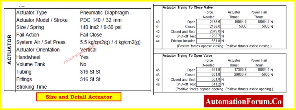
1. Choose Actuator Type: Select a type of actuator. Reliability, response time, and power availability will guide your choice from pneumatic diaphragm, piston, electro-hydraulic, or electric actuator.
2. Calculate Required Thrust/Torque: Calculate necessary thrust or torque by use of vendor data or computation tools; next, compare with actuator capabilities.
3. Define Fail-Safe Action: Choose fail-safe action fail open, fail close, or fail-in-place dependent on safety integrity level (SIL) and control narrative.
4. Specify Stroke & Timing: Indicate stroke length and define open-close cycle duration (e.g., three seconds for an emergency shutdown).
Note: A reliable actuation solution that ensures safe, responsive valve control under all process conditions.
Step 8: Outline Communication & Software Integration

1. Assess Digital Requirements: Based on the DCS/SCADA architecture of the plant, verify the necessity for smart communication protocols including HART, FOUNDATION Fieldbus, or Profibus PA. Verify fit with I/O modules for the control system.
2. Select Configuration Tools: For calibration and diagnostics, name the preferred setup tools such Emerson AMS, Yokogawa PRM, or ValveLink. Check it enables online monitoring and remote parameter access.
3. Document I/O Requirements: Specify an analog or digital control interface, either two- or four-wire, and make sure system validation includes built-in loop integrity checks.
4. Plan Redundancy: For Fieldbus networks, designate redundant bus pathways or dual-ported transmitters should high-availability be required. Record any network zone segregation or firewall as advised by cybersecurity guidelines.
Note: Digital integration of the control valve with DCS is assured, enabling diagnostics, predictive maintenance, and control precision.
Step 9: Define Positioner Requirements

1. Determine Positioner Type: Choose an analog, electro-pneumatic, or digital positioner based on loop performance, control precision, and diagnostics requirements. Check, if digital, local display and auto-calibration tools.
2. Map Control Signal: Specify signal inputs-output mapping, for setpoint 4-20 mA input and for position monitoring 4 -20 mA or HART feedback output
Technical Benefits Explained in: Why You Should Use Control Valve Positioners?
3. Specify Supplemental Features: Describe further characteristics: Indicate for safety integrity checks advanced features including trip limit warnings, diagnostics, split ranging, and partial stroke testing (PST).
4. Document Air Supply Specs: Specify pressure (e.g., 5.5 bar), air consumption, filtering (5 micron or better), and tubing/fitting requirements.
Note: Positioner is correctly configured to ensure stable control loop performance and enhanced valve diagnostics.
Explore the Key Add-Ons in: Essential Control Valve Accessories for Reliable Process Control
Step 10: Integrate Solenoid Valve Details
1. Identify Safety or Logic Needs: One can find safety or logic needs by: Find out if either a manual override for maintenance bypass or an emergency shutdown system includes the solenoid valve. Verify its interlock logical position.
2. Select Model & Interface: Select models whose NAMUR interface fits your IP rating (e.g., IP65 or Ex d), and verify fail-safe de-energized position.
3. Record Coil Specs & Response Times: Record 24 VDC, 110 VAC, opening and shutting times in milliseconds for electrical supplies. Make sure solenoid complies with field wiring regulations.
Note: Reliable responsiveness of the solenoid valve helps remote actuation in safety or shutdown logic.
Prepare for Success with: Essential Control Valve Interview Questions
Step 11: Specify Switches for Feedback
1. Choose Switch Type: Provide the kind of limit switch mechanical or proximity type then make sure the limit switch complies with hazardous area classification, say flameproof, intrinsically safe.
2. Set Actuation Points: Set switch positions for completely open and closed feedback. Where called for, record deadband or hysteresis.
3. Detail Electrical Outputs & Ratings: Check contact type (SPDT, DPDT), switching logic (NO/NC), and max voltage/current handling. Show whether switches link to a safety system or PLC/DCS.
Note: Position feedback for alerts, status, and safety interlock interfaced properly with control systems.
Refer the below link to Your Go-To Resource on: Control Valves in Process Industries: A Collection of In-Depth Articles
Step 12: Prepare Air Set Conditioning

1. Select FRL Unit: Choose an air filter-regulator-lubricator unit fit for the plant instrument air system. Add coalescing filters for either particle or oil removal.
2. Define Air Quality: Specify ISO 8573-1 class based on criticalityCl ass 2.2.2 or better is typically preferred for control valves.
3. Document Tubing & Fittings: Specify tube material (SS 316, nylon), size (e.g., 6 mm OD), and whether compression fittings or push-fit fittings will be used. Verify fittings meet the site environment.
Note: The result is a clean, controlled, properly piped pneumatic air supply that guarantees actuator dependability over long run.
Understand the Core Metrics in: Essential Control Valve Performance Parameters
Step 13: Collate Purchase Details
1. Vendor Pre?Selection: Consult the approved vendor list (AVL) to make sure chosen suppliers satisfy technical criteria and project parameters.
2. Request Quotations: Ask several vendors issue inquiry packets comprising specs, sizing findings, and data sheets. Clarify delivery and commercial terms.
3. Record Lead Times & Costs: Record unit pricing, freight costs, warranty terms, and lead times for leads times and expenses. Relate this to the project procurement calendar.
4. Finalize Purchase Order Details: Work with procurement to match FAT timetable, inspection point system, and Incoterms..
Note: A commercially viable and technically compliant purchase order for the required control valve and accessories.
Step 14: Document Special Requirements
1. Review Project Notes: Cross-check project specifications, safety standards, and end-user requirements for any custom needs (e.g., fugitive emission compliance, local painting standards).
2. Incorporate Mitigation Features: For extreme service applications, provide sound attenuation cages, anti-cavitation devices, or erosion-resistant trims.
3. List Certification Needs: Include NACE MR0175, ATEX/IEC zone classifications, PED/CE marking, SIL certification should application demand it.
4. Append Commissioning/NOC Checks: Specify whether handover documentation includes site acceptance tests (SAT), commissioning/NOC checks, loop checks, or function tests forms part.
Note: Valve is completely compliant with all particular environmental, safety, and regional guidelines for perfect commissioning.
Completion and Validation
1. Cross-Check: Technical documentation, vendor comments, and team validation will help you cross-check every field in the datasheet.
3. Release for Quotation: Send final data sheets to suppliers together with RFQ documentation package.
4. Maintain Revision Control: Log all updates in a document management system using a justification for change and approver signature.
Final Outcome: a validated, whole, project-specific control valve datasheet supporting engineering, procurement, and construction processes.
By following these 14 sequential steps, EPC instrumentation engineers can systematically prepare control valve data sheets that are accurate, vendor-ready, and fully aligned with project requirements.
Best Practices for Engineers in: Control Valve Selection and Recommended Practices for Harsh Process Conditions
Standardized Excel Template for Control Valve Specification, Sizing, and Procurement in Industrial EPC Projects

Refer the below link to download this editable control valve datasheet template for EPC instrumentation projects. It ensures accurate specification, sizing, and documentation.
Test your Knowledge on Control Valve Types, Selection, and Applications
Refer the below link to test your expertise on Control Valve Types, Selection and Applications for Project Engineers