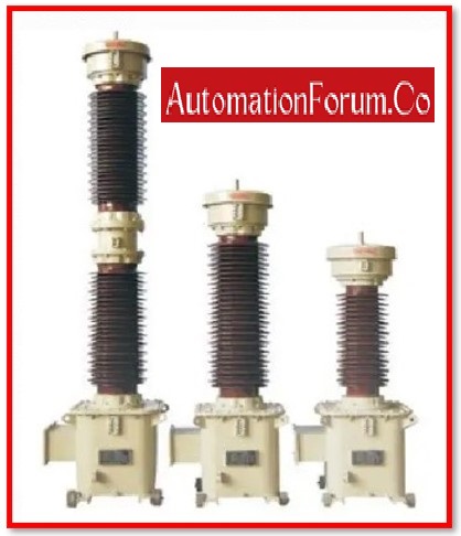
CVT Capacitive Voltage Transformer is a step-down transformer that changes high voltage into low voltage. Capacitor Voltage Transformers transform transmission class voltages into uniformly low, readily measured values that are utilised for high voltage system metering, protection, and control. Normally, it is impossible to detect the line voltage or current in a high voltage system. Because of this, instrument transformers like potential and current transformers are frequently utilised. The cost of a potential transformer is also expensive in EHV lines (Extra High Voltage Lines) due to its insulation. Capacitive voltage transformers are used in place of ordinary voltage transformers to lower the cost of the insulation.
Capacitive potential transformer is another name for the capacitive voltage transformer (CVT). From 72.5 kV and upwards, higher voltage levels employ capacitive voltage transformers (CVTs).
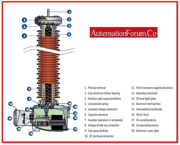
The three primary components of the capacitive voltage transformer are
- Auxiliary transformer,
- Inductive element, and
- Capacitive potential divider.
Why is a CVT required?
The high-insulated transformer is necessary for measuring high voltage over 100 kV. When compared to a standard transformer, the highly insulated transformer is relatively pricey. The technology makes use of a capacitive voltage transformer to reduce costs. The CVT is less expensive than the highly insulated transformer, and it performs similarly.
Working of Capacitive Voltage Transformer:
The auxiliary transformer, the inductive element, and the capacitive potential divider are utilised together. The excess high voltage signals are stepped down into a low voltage signal using the capacitive potential divider. With the help of the auxiliary transformer, the capacitive potential transformer’s output voltage is further stepped down.
The voltage of the line being measured or controlled is placed across the capacitor or potential divider. Place a capacitor across the transmission lines, say C1 and C2. The auxiliary transformer receives its input from the potential divider’s output.
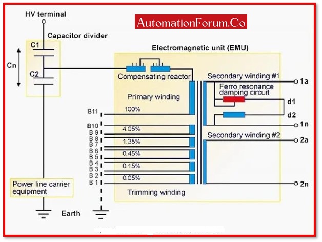
In comparison to capacitors positioned near transmission lines, those placed close to the earth have higher capacitances.
The impedance of that portion of the potential divider becomes low due to the high value of capacitances. Low voltages are thus transmitted to the auxiliary transformer. The voltages are further stepped down by the auxiliary transformer.
The primary and secondary windings of the transformer’s primary and secondary windings, respectively, have N1 and N2 turns each. The potential divider is capacitive, whereas the metre used to measure low voltage is resistive. As a result, there is a phase shift, which has an impact on the output. The auxiliary transformer and inductance are connected in series to solve this issue.
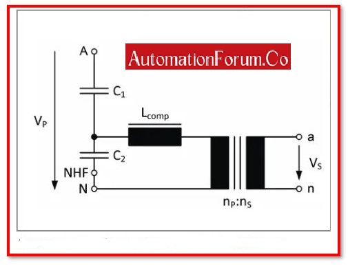
This inductance L is made up of the leakage flux of the auxiliary transformer winding.The inductance value is given as
Inductance values are programmable. Due to the potential divider’s reduction in current, the inductance compensates for voltage drops that occur in the transformer. However, in actuality, the inductance losses make it impossible to provide compensation.
The transformer’s voltage turn ratio is written as
Because C1 has a higher value than C2,
As a result, C1/(C1+C2) has a low value. The voltage is measured at a low level.
The capacitive potential transformer’s voltage transformation ratio is unburdened. The load is something that the transformer’s secondary winding is below.
As the potential transformer is connected across the line to ground, the voltage across each capacitor is V1 and V2, and the voltage across the entire line is Vline/1.732, or Vp.
Apply the potential divider rule to determine the voltage across capacitor C1.
Electrical CVT (capacitive voltage transformer)
The capacitor’s voltage cross-section is V2.
Electrical CVT (capacitive voltage transformer) specifically, V2 V1 because the voltage across C1 is larger than that across C2. As a result, the value C1/(C1+C2) is low. The capacitor C2 is used to produce the low voltage value. The potential transformer makes it simple to scale down low voltage.
CVT characteristics:
- External configuration
- Recognise for the principal international standards
- Film paper synthetic fluid for insulation
- The transformer’s bottom tank contains an electromagnetic component that is mineral oil-insulated.
- External metal components are all made of aluminium alloy.
- A hermetically enclosed structure
- Constant accuracy across the board for all services
- High transient response fidelity and quick ferroresonance oscillation dampening
- Free of maintenance
Advantages of CVT:
- Not even a partial discharge
- Simple commissioning and installation
- lengthy life cycle
Applications of CVT:
- Power systems: A capacitor voltage transformer (CVT or CCVT) is a transformer that steps down extra-high voltage signals and provides a low voltage signal for metering or running a protective relay.
- Voltage Measuring: For the purpose of revenue metering, protection, and control, they precisely reduce transmission voltages to usable values.
- Insulation: The ensure THAT the insulation between the LV circuits and the HV network, assuring the operators of the control room are in a safe environment.
- HF Transmissions: PLC coupling may be accomplished using them.
- Transient Recovery Voltage: CVT’s own high capacitance improves C/B short line fault / TRV performance when put near HV/EHV Circuit Breakers.