What is the motion balance principle and why it is utilized in pneumatic instruments?
Motion balance instruments will create a motion to oppose the input motion. In order to maintain a constant position for the flapper or nozzle in the pneumatic instruments motion balance principle is used. Pneumatic instruments are mostly utilized for measuring purposes and they can measure several parameters such as pressure, flow, level, temperature, etc.
What is the difference between the motion balance and force balance instruments?
In the pneumatic instrument, a flapper nozzle is a major component and its purpose is to measure the minute changes into a signal. A motion balance instrument will create a motion to counteract the input motion. This is done to keep a proper gap in the nozzle. In the case of a force balance instrument force will be created to counteract the input force.
How does a motion balance instrument work?
In most pneumatic instruments motion balance system is utilized. The input signal will make the baffle move close to the nozzle. Due to this, the pressure in the nozzle will be increased and this pressure will make the nozzle move. The nozzle will move upwards till the movement equals the input motion.
What are the different types of motion balance instruments how do they work?
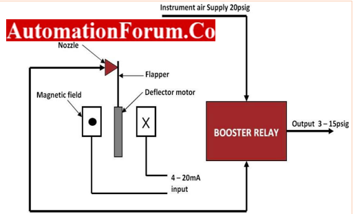
I/P transducers
I/P transducers are utilized in several industrial mechanisms and they can convert electrical signals to pneumatic signals. These transducers are also called current-to-pressure transducers.
- A flapper nozzle system is used in the I/P transducer a balancing mechanism is utilized to create a pneumatic pressure signal from an electric current signal.
- The magnet will get activated because of the current signal. When the coil creates a magnetic field the deflector motor in the coil will oppose the nozzle.
- The deflector motor has a flapper valve and this restriction from the motor will develop backpressure in the booster relay.
- When the input current flows through the coil it will generate a force between the coil and flapper valve. In case the current is high then the magnetic power will be high too.
- The flapper will move close to the nozzle and therefore only less pressure will be escaped from the nozzle and the output pressure is increased.
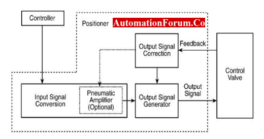
Motion-balanced valve positioner
- Positioners are devices that are used in a control valve to properly position an actuator based on the control signal.
- The valve positioner can make the accurate positioning of the valve stem. Pneumatic input is converted to mechanical motion, this mechanical motion will vary the position of the directional control valve and thus air will be supplied to the actuator.
- In this, the pneumatic signal will be converted to mechanical motion and it is achieved by diaphragm or bellows. The pressure variation will be converted to linear motion.
- This linear motion will be used to position the directional control valve or it will be used to modulate the flapper nozzle. Linear motion will be created by the input signal converter and this will change the position of the flapper.
- Diaphragm will create linear motion due to the variation in the control pressure. This linear motion will be fed to the output signal generator and it will cause the movement of the control valve.
- The movement of the control valve will be opposite to the linear motion and thus it will counteract the input signal. This will be the output signal and the control valve has changed its position.
Pneumatic temperature measuring device
- The pneumatic temperature measuring device will have a sensor and this sensor will be liquid-filled or gas-filled.
- When the sensor in the measuring device senses the input temperature, then this sensor will push the diaphragm and the motion lever.
- The movement in the motion lever will make similar moves in the baffle. The baffle movement will be several times greater than the lever movement.
- The motion of the diaphragm will be increased by the lever. When the baffle is not near the nozzle, then the pressure in the nozzle tube will be reduced.
Pneumatic relay
- A relay is a device that can connect two circuits. In the pneumatic relay, it uses air instead of electrons such as in normal relays for its operation.
- In the pneumatic relay operation when compressed air flows in a circuit, then the energy of this flow of air will activate a switch and then it will flow through the second circuit.
- A pneumatic relay operates in a 3-15Psi pneumatic signal and this signal is capable to control several large devices.
- The movement of the piston actuator in the pneumatic system can be controlled by the relay and this is why it is used for pneumatic operations.
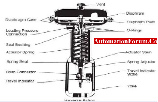
Pneumatic actuator
- Actuators are devices that can automatically position a valve. Actuators are used for valves that are operated remotely.
- These actuators will create force from a small variation in pressure.
- These actuators will convert the energy created by a vacuum or compressed air to a linear or rotary motion.
- In this type of actuator, there is a piston inside a hollow cylinder. The position of the piston will be changed due to the pressure from a pump or compressor.
- When the pressure increases the cylinder will move at a similar axis to the piston and thus a linear force will be created.
- The piston will reach its original position because of a spring back force or due to the fluid which is supplied to the piston.
- The major advantage of the pneumatic actuator is that it can create accurate linear motion. We can use pneumatic actuators for extreme temperature applications.