- What is impulse piping?
- What are the things to remember before designing a impulse line
- Impulse line installations
- What are the problems caused in the impulse lines?
- Key Design Considerations Before Installing Impulse Lines
- Impulse Line Installation Guidelines (Slope and Layout)
- Impulse Line Design Checklist for Engineers
- Installation Best Practices and Maintenance Tips for Impulse Lines
- How Does an Impulse Line Work?
- Components of an Impulse Line System
- Impulse Line Material Selection
- Impulse Line Sizing Guidelines
- Common Impulse Line Installation Mistakes
- Impulse Line Maintenance Checklist
- Impulse Line Troubleshooting Guide
- Heat Tracing for Impulse Lines
- Engineering Best Practices for Impulse Line Design
- Frequently Asked Questions (FAQs) on Impulse Tubing and Piping
- What is an impulse tube?
- What is the purpose of impulse tubing?
- What is the difference between a capillary tube and an impulse line?
- What is an impulse line in process instrumentation?
- What is the recommended slope for impulse tubing?
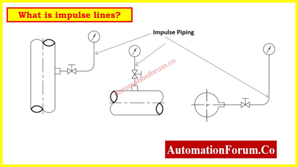
What is impulse piping?
An impulse line is a small-gauge pipe that is used to connect a point in a pipe in which the pressure is measured at a
instrument. In flow measurement using a primary device such as an orifice plate, nozzle or Venturi meter, impulse lines are used to connect upstream and downstream (or throat) points of the meter to a secondary device for measuring the differential pressure.
What are the things to remember before designing a impulse line
• Impulse-line diameter and length
• Location of the secondary device relative to the primary device
• Routing of the impulse lines between the primary and secondary devices, including the slope
• Location of pressure tappings
• Effects of ambient temperature, temperature gradients and fluctuations, and the associated need for heating
or insulation
• Fluid in the impulse lines
• Valves and connections for venting and draining
• Isolation valves
• Avoiding impulse-line blockages
Impulse line installations
The secondary instrument relative to the primary instrument imply that gas filled impulse lines should slope upwards from the pressure tappings to the transducer and liquid-filled lines should slope downwards
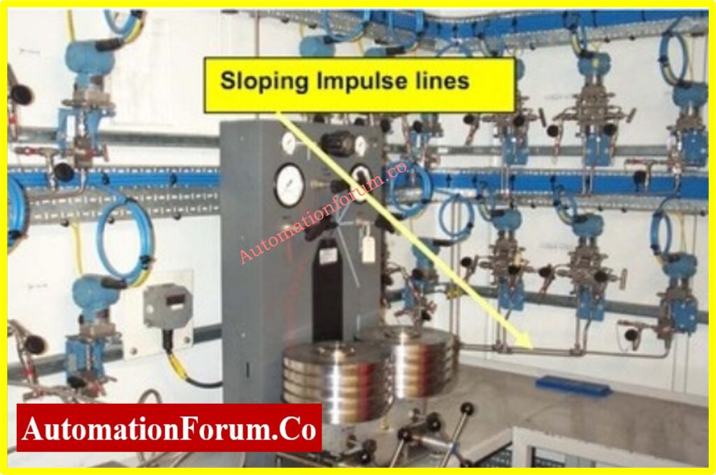
Figure below shows an enclosure with three differential-pressure transmitters and one static-pressure transmitter. The enclosure contains a heater (behind the transmitters in the middle of the picture). The three differential-pressure transmitters are mounted on a mono-block. Where high-static calibration is performed off site and footprinting is the norm on site then small enclosures are not a problem since if the transmitters are mono-block-mounted the complete block with transmitters mounted is removed for remote calibration, and footprinting can be performed in situ on site with very little problem. The mono-block also has a stabilizing effect with regard to temperature. Where a number of transmitters are connected via pipework it is prudent to keep the distance between transmitters as small as possible. On some gas systems where three or more transmitters are used and the distance between the transmitters is about 1 m there is a problem with gas noise; the signal from the end transmitter may be reflected so as either to increase or to decrease the signal strength at the first transmitter. This causes problems where the accuracy of the measured differential pressures is checked by a comparison between pairs of transmitters, and alarms are set. Thus close coupling between such transmitters is very desirable

If the impulse lines are filled with liquid, it is possible that this liquid will freeze in cold weather conditions. This possibility depends, of course, on the type of liquid that fills the impulse and cold weather lines in that geographic location.
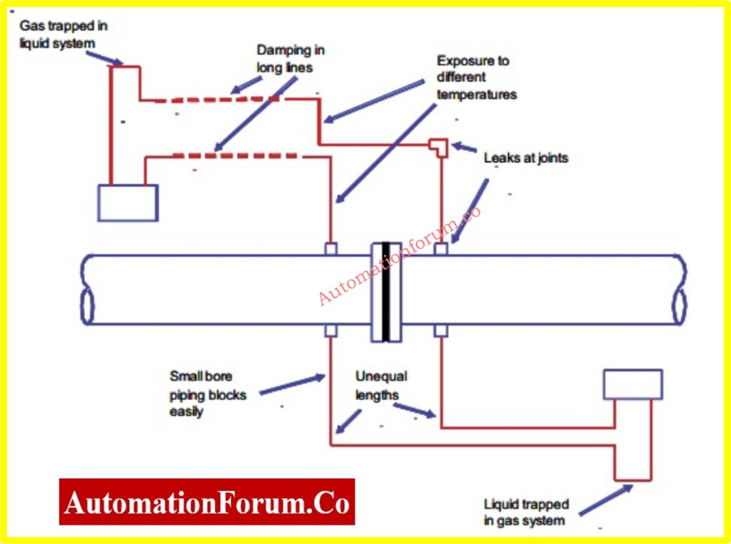
What are the problems caused in the impulse lines?
The use of impulse lines is known to cause a number of problems that can lead to an incorrect measurement. The
problems can arise from the following:
1. Damping of the pressure signal or resonances (this problem is exacerbated if a transient measurement is required
or if the lines are of different length)
2. Blockage
3. Leakage at couplings
4. Different temperatures (and therefore different densities) in a pair of impulse lines
5. The fluid in the impulse lines being of a different composition from the fluid in the pipe (this causes a particular
problem in a vertical meter when a gravity head correction or some other approach is required)
6. Condensation in an impulse line that is intended to be filled with gas
7. Gas bubbles being trapped in an impulse line that is intended to be filled with liquid, or boiling of a liquid with a
bubble point below the ambient temperature
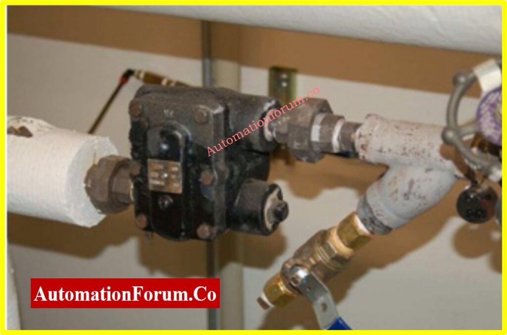
One protection against the impulse line is to trace the impulse lines with some form of active heating, with steam and electric being the most common. The “vapor tracing” consists of a copper tube that transports steam at low pressure, wrapped together with one or more impulse tubes, enclosed in a thermal insulating jacket.
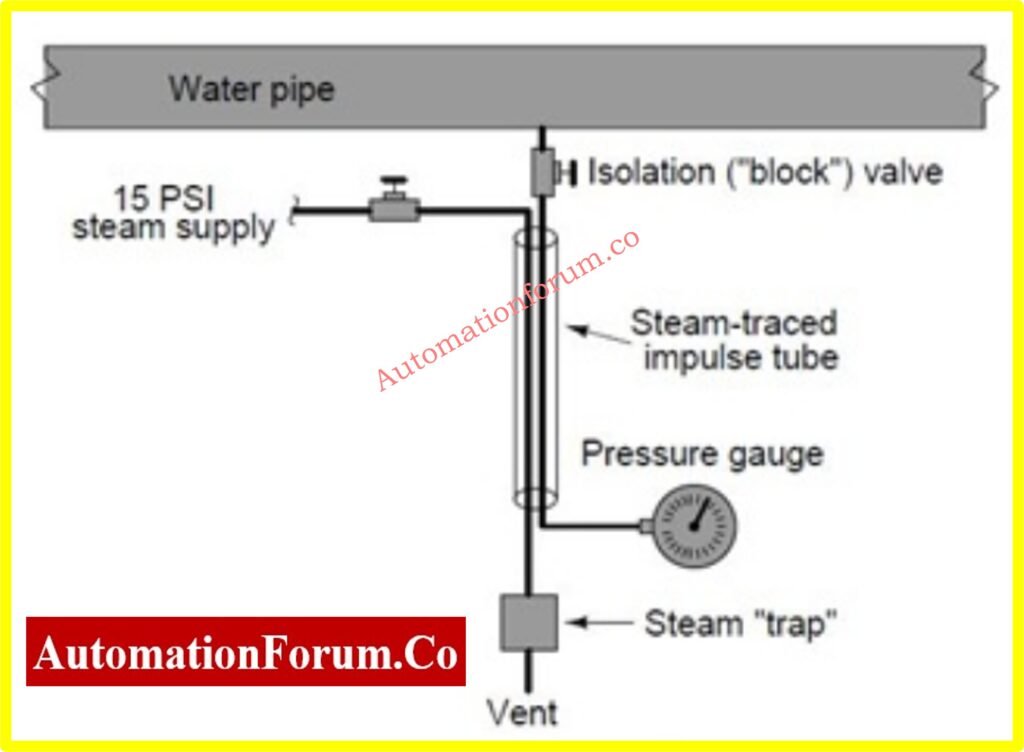
The steam flows through the shut-off valve, through the tube in the insulated package, transferring heat to the impulse tube as it passes. The cooled vapor condenses in water and accumulates in the vapor trap device located at the lowest elevation in the steam tracing line. When the water level accumulates to a certain level within the trap, a floating valve opens to vent the water. This allows more steam to flow into the tracking tube, keeping the pulse line continuously hot. The steam trap also acts as a kind of thermostat, although it only detects the condensed water level and not the temperature. The speed at which the steam condenses in the water depends on how cold the impulse tube is. The colder the impulse
Tube (caused by colder environmental conditions), more heat energy extracted from the steam, and consequently, the faster rate of steam condensation in the water. This means that water will accumulate faster in the steam trap, which means it will “purge” more often. The most frequent purge events mean a higher vapor flow in the tracking tube, which adds more heat to the tube bundle and increases its temperature. Therefore, the system is regulated naturally, with its own negative feedback cycle to maintain the temperature of the package at a relatively stable point5.
The following photograph shows an image of a steam trap:
The steam traps are not infallible, they are susceptible to freezing (in very cold climates) and they open (using steam when venting it directly into the atmosphere). However, they are generally reliable devices, capable of adding enormous amounts of heat to the impulse tubes to protect them against freezing.
Power trace lines are an alternative solution for cold weather problems. The “path” used is a double cable (sometimes called heat tape) that acts as a resistive heater. When energy is applied, the cable is heated, imparting thermal energy to the impulse pipe with which it is included. The following photograph shows the end of a section of electric heating tape, with a power of 33 watts per meter (10 watts per foot) at 10 degrees Celsius (50 degrees Fahrenheit):
Both steam and electrical heat tracing are used to protect instruments themselves from cold weather freezing, not just the impulse lines. In these applications it is important to remember that only the liquid-filled portions of the instrument need freeze protection, not the electronics portions
Key Design Considerations Before Installing Impulse Lines
When constructing impulse lines, keep these engineering factors in mind:
- Line diameter and length
- Slope direction and ratio (1:10 recommended)
- Location of tapping points
- Ambient temperature and the need for insulation or heat tracing
- Fluid type (gas, liquid, or steam)
- Valve and manifold arrangements for venting and draining
- Accessibility for maintenance
- Avoiding vibration and mechanical stress
Impulse Line Installation Guidelines (Slope and Layout)
To get an accurate measurement:
- Gas service: From the tapping site, run the impulse lines up to the transmitter at a 1:10 slope.
- For liquid service, draw lines down from the tapping point to the transmitter at a 1:10 slope.
- Try to keep lines as small and straight as you can.
- To avoid signal lag, make sure that the lengths of the differential pressure impulse lines are the same.
- Support lines tightly to cut down on vibration and tiredness.
Recommended Impulse Line Slopes
| Service Type | Slope Direction | Ratio | Purpose |
| Liquid | Downward | 1:10 | Prevent air pockets |
| Gas | Upward | 1:10 | Prevent condensate accumulation |
| Steam | Condensate leg | As per design | Maintain condensate seal |
Impulse Line Design Checklist for Engineers
| Design Parameter | Recommended Practice | Issue if Ignored |
| Diameter | 6–12 mm (¼–½ inch) | Signal damping |
| Line Slope | 1:10 (gas ↑ / liquid ↓) | Trapped air or condensate |
| Line Length | As short as possible | Measurement lag |
| Material | SS 316 / Cu-Ni | Corrosion or leakage |
| Insulation | Required in cold zones | Freezing |
| Support | Rigid clamps at intervals | Fatigue or leaks |
| Equal Length (DP lines) | Mandatory | Zero shift or error |
| Valves | Install near tapping point | Difficult draining/venting |
Installation Best Practices and Maintenance Tips for Impulse Lines
Even though impulse lines are easy to build, they need to be installed and maintained carefully to make sure that pressure or flow measurements are always precise and trustworthy. Routing and support are very important. The lines need to be well-supported so that they don’t get tired from vibrating, which could cause them to break or leak over time. Also, the impulse lines should be as short and straight as possible, with as few bends and changes in height as feasible. These can cause measurement lag or inaccuracy.
It is very important to examine and clean often, especially when working with unclean fluids, slurries, or when condensation and freezing are a problem. Blockages happen a lot, and even small ones can mess with differential pressure readings. Using manifolds that have built-in flushing and venting systems can make maintenance a lot easier and cut down on downtime.
If possible, think about putting transmitters in a well-insulated box that is far away from the rest of the equipment, especially in dangerous or severe locations. This makes it easy to keep things running and keeps delicate electronics safe from harsh temperatures and corrosive environments.
Finally, keeping track of installation details such line length, slope, insulation method, and valve placements makes that everything is done the same way every time and makes it easier to fix problems. Impulse pipe systems can work accurately and for a long time, even in tough situations, if they are designed, installed, and maintained correctly.
How Does an Impulse Line Work?
An impulse line transfers process pressure from the process tapping point to the sensing element of a pressure transmitter or differential pressure transmitter without exposing the instrument directly to the process. The pressure inside the process pipeline is transmitted through the impulse tubing, allowing the transmitter to accurately measure pressure, differential pressure, flow, or level.
For differential pressure applications such as orifice plates, Venturi tubes, and flow nozzles, two impulse lines are installed. One line connects the high-pressure side, while the other connects the low-pressure side of the primary element. The transmitter measures the pressure difference between these two lines to calculate the required process variable.
A properly designed impulse line ensures minimal pressure loss, prevents trapped gas or liquid, reduces response time, and provides stable and repeatable measurements even under varying process conditions.
Components of an Impulse Line System
An impulse line system consists of several components that work together to transmit process pressure accurately from the process pipeline to the measuring instrument.
| Component | Purpose |
| Process Tapping Point | Collects process pressure from the pipeline or vessel |
| Root Valve | Isolates the impulse line from the process |
| Impulse Tubing | Transfers process pressure to the transmitter |
| Manifold | Allows isolation, equalization, venting, and calibration |
| Pressure Transmitter | Converts process pressure into an electrical signal |
| Vent Valve | Removes trapped gas during commissioning |
| Drain Valve | Removes accumulated liquid or condensate |
Each component plays a critical role in maintaining measurement accuracy and simplifying maintenance operations.
Impulse Line Material Selection
Selecting the correct impulse tubing material is essential for ensuring long service life, corrosion resistance, and measurement reliability.
| Material | Typical Application |
| Stainless Steel 316 | General industrial process plants |
| Stainless Steel 304 | Mild corrosive services |
| Copper | Pneumatic and low-pressure air systems |
| Monel | Marine and seawater applications |
| Hastelloy | Highly corrosive chemical processes |
| PTFE-lined Tubing | Aggressive chemical applications |
Material selection should consider process temperature, pressure, corrosion resistance, compatibility with the process fluid, and environmental conditions.
Impulse Line Sizing Guidelines
The diameter and length of impulse tubing directly affect transmitter response time and measurement accuracy.
General engineering recommendations include:
- Use 6 mm to 12 mm (¼ to ½ inch) tubing for most industrial applications.
- Keep impulse lines as short as practical.
- Maintain equal lengths for differential pressure impulse lines.
- Minimize bends and unnecessary fittings.
- Support tubing adequately to prevent vibration-induced fatigue.
Proper tubing sizing minimizes pressure losses, reduces signal damping, and improves overall measurement performance.
Common Impulse Line Installation Mistakes
Many instrumentation measurement problems originate from poor impulse line installation rather than transmitter failure.
Common installation mistakes include:
- Incorrect impulse line slope
- Unequal impulse line lengths in DP measurements
- Excessive tubing length causing response delay
- Sharp bends restricting fluid movement
- Unsupported tubing leading to vibration damage
- Missing drain or vent valves
- Improper manifold installation
- Inadequate insulation in cold climates
- Using incompatible tubing materials
- Poor routing that creates condensate traps
Avoiding these mistakes significantly improves transmitter accuracy and reduces maintenance requirements.
Impulse Line Maintenance Checklist
Routine maintenance of impulse tubing prevents measurement errors and unexpected instrument failures.
Maintenance activities should include:
- Inspect tubing for leakage.
- Check all compression fittings.
- Verify impulse line supports.
- Remove blockages by flushing.
- Drain accumulated condensate.
- Vent trapped air before commissioning.
- Inspect insulation and heat tracing.
- Verify manifold operation.
- Check for corrosion and mechanical damage.
- Calibrate the transmitter after maintenance.
Preventive maintenance extends instrument life and improves process reliability.
Impulse Line Troubleshooting Guide
| Problem | Possible Cause | Recommended Solution |
| Unstable pressure reading | Air bubbles or vibration | Remove trapped air and improve support |
| Slow transmitter response | Long impulse tubing | Reduce tubing length |
| Zero shift | Unequal liquid head | Balance impulse lines |
| No pressure reading | Blocked impulse line | Flush or replace tubing |
| Pressure drift | Leakage | Tighten fittings or replace damaged tubing |
| Frozen impulse line | Low ambient temperature | Install heat tracing and insulation |
| Incorrect DP reading | Unequal tubing lengths | Use equal-length impulse lines |
Heat Tracing for Impulse Lines
Impulse lines installed in cold environments are susceptible to freezing, causing blocked pressure transmission and incorrect measurements. Heat tracing prevents freezing by maintaining the temperature of the process fluid within the tubing.
Two common heat tracing methods are used:
Steam Heat Tracing
Steam tracing uses low-pressure steam tubing installed alongside the impulse line. Heat is transferred continuously to prevent freezing and maintain process temperature. Steam tracing is widely used in refineries, petrochemical plants, and power stations.
Electric Heat Tracing
Both methods should be combined with proper thermal insulation to maximize efficiency and reduce energy consumption.
Engineering Best Practices for Impulse Line Design
To ensure long-term measurement accuracy and reliable instrument performance, engineers should follow these best practices during impulse line design and installation:
- Maintain a continuous 1:10 slope appropriate for the process fluid.
- Keep impulse lines as short and straight as possible.
- Ensure equal impulse line lengths for differential pressure applications.
- Install root valves close to the process tapping point.
- Provide drain valves for liquid service and vent valves for gas service.
- Select tubing materials compatible with the process fluid and environment.
- Protect impulse lines using insulation or heat tracing where freezing is possible.
- Secure tubing with proper supports to eliminate vibration.
- Leave adequate access for calibration and maintenance.
- Periodically inspect, flush, and test impulse lines to prevent blockages and maintain measurement accuracy.
These engineering practices help minimize measurement errors, reduce maintenance costs, and improve the overall reliability of pressure, flow, and level instrumentation systems.
Frequently Asked Questions (FAQs) on Impulse Tubing and Piping
What is an impulse tube?
An impulse tube, which is sometimes called impulse piping, is a pipe or tubing with a tiny diameter that is mostly employed in process instrumentation. Its main job is to send pressure from a process line to a measuring equipment, like a differential pressure transmitter or a pressure transmitter. This configuration keeps the measurement tool separate from the main process fluid, which makes it safer and easier to get to. People occasionally mix up impulse tubes with water distribution systems, although in industrial instrumentation, they are only used to send process variables like pressure.
What is the purpose of impulse tubing?
Impulse tubing connects the process medium to the measuring equipment in a physical way. It sends the pressure signal from the process line to the pressure-sensing element without letting the instrument come into direct contact with the flow. These lines can get blocked in some places, especially when it’s cold, because fluids freeze or sediments build up. Proper design and upkeep assist make sure that signals are clear and measurements are correct.
What is the difference between a capillary tube and an impulse line?
The main distinction is how they are built and what they do:
Impulse lines are usually stiff metal tubes that send process pressure directly to the sensing diaphragm inside the instrument. The impulse line is in direct touch with the process fluid.
On the other hand, capillary tubes are flexible and are utilized in systems that seal things from a distance. A diaphragm seal filled with a transfer fluid keeps the measuring equipment and the process apart, so the instrument and the process medium don’t touch each other directly. This configuration is perfect for fluids that are caustic, hot, or very thick.
What is an impulse line in process instrumentation?
An impulse line is a small-bore pipe or tubing that connects a process tap point to an instrument, like a pressure or differential pressure transmitter. It functions as a conduit, sending process pressure from the main line to the instrument so that it may measure accurately while keeping the device safely out of the process line. This configuration is very important for things like employing orifice plates, Venturi tubes, or nozzles to quantify flow..
What is the recommended slope for impulse tubing?
To keep condensate or air pockets from building up, impulse lines should be put in with the right slope. A good rule of thumb is to keep the slope at 1:10, which means that for every 10 units of horizontal run, there should be 1 unit of vertical drop. For liquid service, the lines should slope down from the tapping point to the transmitter. For gas service, they should slope up. To keep traps from forming that could make it hard to send appropriate pressure, stay away from sharp bends or low points in the line.