Table of Contents
- Why are Lambda sensors fitted?
- What does the lambda sensor do?
- How does the lambda sensor work?
- Zirconia Binary type
- Titania Type
- ZFAS-U Type (Air/Fuel Sensor)
- How to test Lambda sensors?
- Procedure for testing the lambda sensor’s functionality
- Signal from the Zirconium sensor before the catalytic converter
- Signal from the Zirconium sensor after the catalytic converter
- Signal from the Titanium sensor before the catalytic converter.
- Signal form the wideband oxygen sensor
Why are Lambda sensors fitted?
- The importance of reducing the emissions produced by internal combustion engines is growing as more vehicles are used on our roadways.
- Governments have adopted ever stronger exhaust gas pollution regulations in an effort to promote the advances in technology that can make this possible.
- Lambda sensors are a crucial component of the technology needed to meet these legal targets, and because of how they work, engines are able to operate at their peak efficiency and performance levels.
- Most petrol-powered automobiles sold after the end of 1992 will be equipped with Lambda sensors.
What does the lambda sensor do?
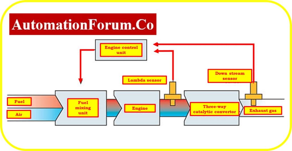
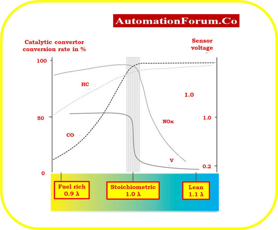
- The three-way catalyst (catalytic converter), which reduces engine emissions, is the most common technique employed by manufacturers.
- The three major toxic gases produced by an engine—carbon monoxide (CO), nitrogen oxides (NOx), and hydrocarbons (HC)—can be converted by this technology into the far less dangerous, non-toxic gases carbon dioxide (CO2), water (H2O), and nitrogen (N2).
- The catalyst must work within a specific temperature range and be supplied with exhaust gases that adhere to very strict specifications that are mostly based on the air/fuel ratio in order to carry out this conversion of gases effectively.
- An exhaust gas oxygen (Lambda) sensor positioned upstream of the catalyst provides the exact control necessary to run this system.
- The air/fuel ratio present in exhaust gases can be precisely measured by a lambda sensor.
- The fueling system can continue to operate within the necessary, extremely tight tolerances by sending a signal to the control unit, which can then start a change. This type of control system is known as a closed-loop control system.
- Most vehicles built after 2000 have an additional Lambda sensor installed downstream of the catalyst to monitor the catalyst’s operation, which helps to further improve management of exhaust emissions.
How does the lambda sensor work?
- Zirconia sensors and Titania sensors make up the majority of Lambda sensors and are not interchangeable.
- These fall under the category of binary or Lambda 1 sensors. They perform in various ways and employ various sorts of ceramic elements, but they all work towards the same objective: ensuring that the catalyst operates effectively and those dangerous gases are kept to a minimum.
- An engine must achieve close to full combustion in order to accomplish this.
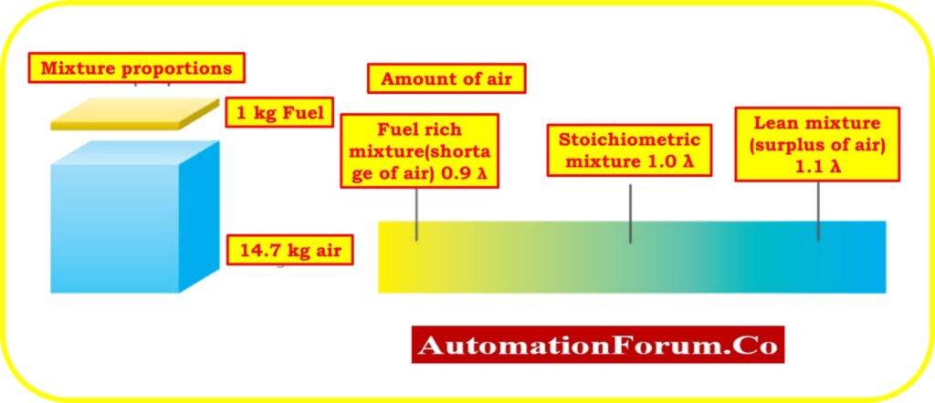
- To accomplish this, an optimal air to fuel ratio of about 14.7:1 must be employed, which means that 1 kg of fuel must be used for every 14.7 kg of air. A stoichiometric ratio, or Lambda (?))1.0, is the name for this chemically ideal air-fuel ratio.
- A fuel lean mixture would have a higher value, such as 1.2, while a fuel rich mixture would have a lower value, such as 0.8.
- The number of vehicles using sensor types that can accurately monitor the air/fuel ratio over a wide range of fuel rich and fuel lean conditions is still relatively modest, but it is growing.
- These sensors are wideband, broadband, or linear types and are known as UEGO (Universal Exhaust Gas Oxygen) sensors.
Zirconia Binary type
- The sensor has a ceramic body in the shape of a hollow thimble composed of zirconium dioxide underneath the metal protecting end.
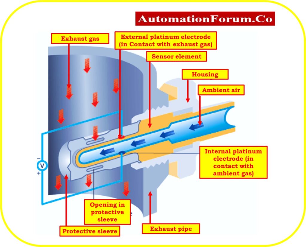
- Specially crafted perforations in the protective metal shell allow the exhaust gases to make contact with the ceramic element’s surface. This ceramic element has a thin platinum layer that is microporous on both sides.
- The electrodes in these layers are what transmit the sensors’ signal to the wire cables.
- To shield the platinum from erosion by the exhaust fumes, a thin extra layer of porous ceramic is put over the outer electrode.
- The thimble’s inside is hollow, and it is used to store room air as a reference gas.
- The zirconia element contains a characteristic that causes oxygen ions to transfer at temperatures higher than 300°C. A voltage is created by this motion.
- The voltage generated increases with the amount of oxygen concentration differential between the exhaust gas and ambient reference air in the sensor thimble’s core.
- The voltage generated should be roughly 0.1 volts in the fuel lean position and 0.9 volts in the fuel rich position.
- The fact that there is a rather big change in voltage at or near the stoichiometric point makes this function extremely useful.
- By continuously returning the fueling system from a fuel lean or fuel rich state to maintain the stoichiometric mixture, the sensor is able to maintain the engine emissions within strict limits. About 300 milliseconds pass between fuel lean and fuel rich transitions.
- After starting the engine, the fueling system is not being managed as precisely as we would like because this switching procedure won’t start until the sensor is up to working temperature.
- Unwanted emissions might grow as a result of this. Heated exhaust gas oxygen (HEGO) sensors are utilized to overcome this delay.
- Due to the heating element that is located in the middle of the thimble on these sensors, strict fueling management may begin very fast after the sensor has reached operating temperature.
- The temperature of exhaust gas might decrease dramatically when a vehicle is idle; heated sensors make sure that this temperature drop won’t hinder the sensor’s ability to function steadily.
Titania Type
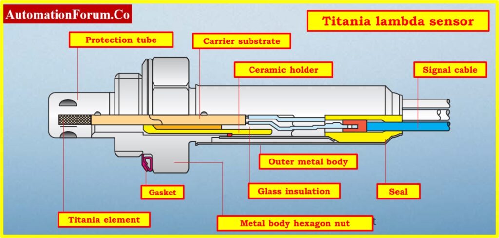
- These sensors like zirconia-type sensors from the outside, but the sensor body might be generally smaller.
- The electrical resistance of the titania changes in accordance with the oxygen level of the exhaust gas in these sensors instead of producing a voltage as in the zirconia type.
- The element resistance increases when there is an excess of oxygen in the exhaust gas (fuel lean), and lowers when there is a deficit of oxygen (fuel rich).
- There is a noticeable change in resistance at the stoichiometric point. As a result, the output of an applied voltage will vary depending on the fueling situation.
- The sensor can be smaller, stronger, and have a quicker response time since there is no requirement for a pocket of air to serve as a reference gas and because of other design variations.
- In comparison to the zirconia kind, this sensor’s control scheme is considerably dissimilar. Internal heating elements are present in every titania type sensor.
ZFAS-U Type (Air/Fuel Sensor)
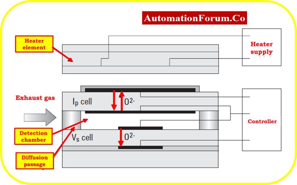
- This sort of sensor is also referred to as a UEGO, wide band, or linear sensor.
- The simplest method to recognise this type of sensor is by the quantity of lead wires, which must always be at least five. The Zirconia detecting element and the Alumina heating element are ceramic substrate components that are stacked together to form the sensor.
- Since the sensor produces its own reference air, no external source is needed. A gas diffusion layer exposes the detecting cavity to exhaust gas.
- Simply said, by pumping oxygen into or out of the sensing chamber, the sensor aims to maintain a stoichiometric air/fuel ratio.
- The amount of pumping current necessary to achieve this correlates to the exhaust gas’s air/fuel ratio.
- This kind of sensor not only has a wide measuring window and works well in lean burn scenarios, but it also offers outstanding precision around the stoichiometric threshold, which is helpful in the effort to reduce emissions.
- Diesel engines will also utilize this kind of sensor because they have an excess air factor.
How to test Lambda sensors?
Procedure for testing the lambda sensor’s functionality
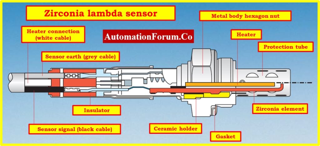
- Determine the terminals. Depending on the system being evaluated, a sensor may have a single, double, triple, or quadrupled terminal:
Ground for the oxygen sensor heater (white);
Positive power oxygen sensor heater (white);
Lambda probe signal (often a black cable);
Lambda probe ground (often gray).
- If there is a heater for the oxygen sensor, check it. Verify that the heater’s source is 12V, the same as the car battery.
- Check the wiring to the ignition key relay if there is no voltage. Check the ground connection of the oxygen sensor heater.
- The engine should be started and heated to operating temperature.
- Keep the engine running for 30 seconds at 3000 rpm. The sensor will become hotter as a result, turning it on.
- Hold the engine at 2500 rpm. The oxygen sensor will cool and turn off if the engine is left idle for a long time.
- Note that an incorrect thermostat prevents the performance of this test.
- Determine whether the oxygen sensor is wideband, zirconium, or titanium.
- Verify the oxygen sensor’s output signal the sensor
Signal from the Zirconium sensor before the catalytic converter
- The digital voltmeter will display an average value, such as 450mV. Although the voltage may be slightly higher, the “slow” oxygen sensor can turn on properly without being detected.
- The oscilloscope is typically the best tool for identifying problems. A voltmeter or a fault code reader should not be used.
- When the engine is in idle mode, a continuous, nearly sinusoidal waveform fluctuation with a frequency of 1Hz–5Hz can be seen on the oscilloscope screen if the sensor is functioning properly.
- The signal’s ranges from 0.1V at its lowest point to 0.9V at its highest point. There will be about 0.45V of variations on average.
- The signal edges don’t last more than 250ms. At higher engine speeds, the same signal should be seen at a higher frequency.
Signal from the Zirconium sensor after the catalytic converter
- The oxygen sensor signal from a catalytic converter that is operating properly will be a straight line at a level of 0.5–0.6 V.
- A digital voltmeter can also be used to measure output voltage.
- The catalytic converter is not functioning properly if the signal fluctuates and resembles the signal from the sensor before the catalytic converter in terms of shape.
Signal from the Titanium sensor before the catalytic converter.
- When the engine is running at idle, a fully functioning sensor will produce signal variations that range from 0.2 to 4.5 volts and have sharper edges than those of a zirconium sensor. An average value of about 2V will be displayed by a digital voltmeter.
Signal form the wideband oxygen sensor
- The wide band sensor employs two wires and signals the computer using a current flow as opposed to narrow band sensors, which communicate with it using a voltage on a single wire.
- It is generally agreed that the ideal air/fuel ratio is 14.7 to 1 (by weight). The current flows in one direction when the ratio is above this value and in the opposite direction when it is below this value.
- The exact air/fuel ratio of 14.7 to 1 causes no current to flow at all. The current flow increases in proportion to how rich or lean the air/fuel ratio is to signify increasingly rich or lean situations.
- The current pumping wires are the two wires. Manufacturers use different voltages for these current pump cables. The ECU will supply the sensor with electricity through one of the two current pump lines. The return wire from the sensor to the ECU will be on the other wire. Toyotas have a reference wire with a voltage of 3.0 volts and a current return wire with a voltage of 3.3 volts. The 3.3 volts will alter slightly as the current flows, but only by very small amounts. Nissans use 2.7 volts for their reference wire and about 3.0 volts for the current wire.
- The difference between the two current pump wires has, so far, been a nominal.300 (300 millivolts), which varies slightly depending on current flow, in all of the 4-wire wide band sensors we’ve observed.
- Another variety of wide band sensor employs 5 wires, and sometimes (rarely) 6 wires.
- In this instance, there is an additional wire that represents the current flow on the current pump wires as a voltage.
- A fifth wire will typically be referred to as the “signal wire” when it is utilized in this manner.
- Additionally, a ground reference for the signal cable is provided by the 6-wire variants.
- Circuitry is present in both of these instances to transform the current flowing through the current pump wires into a voltage. But the voltage on the fifth wire is still managed by this type using the current pump pair of wires.
- Attach the signal wire terminal on the sensor with a clip to the positive multimeter lead. Out of the five terminals, the signal wire terminal is the middle one (third from the side).
- Ground the negative multimeter lead with a clip. The negative battery terminal or the engine’s or manifold’s metal surface are examples of grounded points.
- Start the car’s engine, then let it idle for a full minute.
- Keep an eye on the multimeter; it should read between 1 and 5 volts. If you aren’t getting a reading, the sensor is likely broken and needs to be changed.