- What is the purpose of panels and why is it important for automation design?
- What are the different types of panels required for an automation design?
- Marshalling cabinet
- Major components of the marshalling cabinet
- Input and output barrier cards
- Functions
- Marshalling cabinet requirements
- System cabinet
- Combined cabinet
- Network cabinet
- Major components of networking cabinet
- Power distribution cabinet
- UPS and Non-UPS power supply
- How to do the cable interconnection in the automation panels?
- Cable tagging
- Where should we do cable tagging?
- Cable testing before installation
- Cable testing after the installation
- Cable ferruling
- Cross ferruling
- Environmental and Safety Considerations for Panel Design
- Grounding and Earthing in Automation Panels
- Cable Management in Automation Panels
- Labeling and Documentation for Panels
- Maintenance and Inspection of Automation Panels
- What are the different types of automation panels?
- What are the different parts of automation?
- What is the automation design process?
Automation plays a major role in industrialization, automation can be used to control industrial machinery. It is used to do different industrial processes and due to this, the manpower required for the industrial process is reduced. The major advantages of automation are increased productivity, reduction of labor cost, safety in the working environment, and also there is a great improvement in product quality.
What is the purpose of panels and why is it important for automation design?
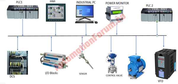
The major requirement of the panel in an automation design is to integrate all the devices and components in an industrial system. The industrial system will be composed of various devices and components such as PLC, HMI, industrial PC, DCS, I/O blocks, actuators, sensors, alarms, etc. So, all these components are automated, the interconnection of these components is done with help of certain panels such as system cabinet, marshaling cabinet, etc. These cabinets would simplify the wiring of different devices and also the communication between devices or components can be done because of these panels. We can remotely control many devices with the help of the interconnection provided by these panels. We could control a process in an automated system due to the interconnection of different devices and components.
What are the different types of panels required for an automation design?
All the cabinets would have four cooling fans and also would have filters. Cabinets also would have a ventilation system so that they can extract the heat produced by the electronic circuits
- Marshalling cabinet
- System cabinet
- Networking cabinet
- Power distribution cabinet
Marshalling cabinet
Mostly, these panels are used as an interface between the field junction box and the DCS control panel. There could be many transmitters in a process plant and if we try to wire it directly to the control room then it will be really difficult to manage and due to this these transmitters are wired and terminated to the field junction box. There could be a huge number of junction boxes in a process plant and these junction boxes would be connected to a certain number of field devices. So we cannot wire this much cable to the control room and that’s where we could use the marshalling cabinet to terminate these main cables.
This cabinet would terminate the main cables and then the field devices would be connected to the specific I/O cards. There would be internal wiring to further connect it from the marshalling cabinet to the system cabinet. There will be input-output barrier cards in the marshalling cabinet. A barrier is an isolator that will safeguard the system side from any unwanted current from the field devices side. Barriers can be seen in the marshalling cabinet and it would protect the field devices and also the system by grounding the excessive current. Marshalling cabinet would have a lot of input/output barrier cards and it will be used to install the input-output barrier
Major components of the marshalling cabinet
- Isolators
- Relay
- Barrier
- Field termination assembly
- Terminal block
- Diode Oring
- Shield terminals
- Power supply module
Input and output barrier cards
The input barrier cards would prevent the excess current which comes from the field. The output barrier cards would prevent the excess signal that goes to the field. All the output signals which go to the field would go through this output barrier card.
The major purpose of a marshalling cabinet is to group the I/Os. So it would group the I/Os such as analog input, analog output, digital input, digital output, and also the pulse I/O. The I/O signals would be transmitted to the system CPU/controller through the isolation signal controller.
Functions
- Signal conditioning
- Termination
- Signal isolation
- Cold junction compensation
- Field device power supply
Marshalling cabinet requirements
- Incoming field cables must be terminated on terminal strip only
- Prefabricated cables with connectors must be laid from the marshalling cabinet to the system H/W cabinet. So the relays, barriers, etc, must be mounted on the marshalling racks.
System cabinet
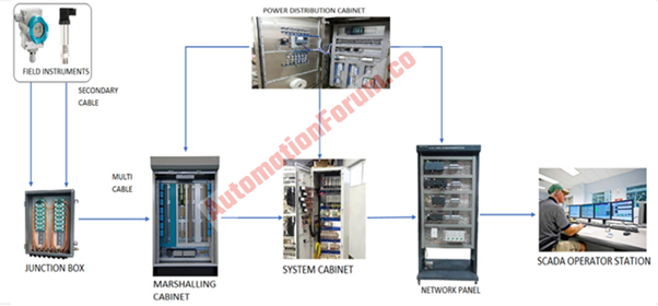
The system cabinet is composed of analog I/O cards, CPU cards, and also communication card. The system hardware would be mounted to this cabinet, the system cabinet would be composed of bus bars of different voltage levels for power distribution. The field devices would be connected to the system cabinet through the marshalling cabinet as we discussed earlier. From the system cabinet, it will be connected to the network cabinet. So the connection of the field device to the system cabinet is achieved with the help of marshalling cabinet and we can see both these cabinets in the rack room. In the above image, we can see the field instruments are connected to the junction box and from there the connection and termination are achieved with the help of marshalling cabinet. The signal would be transmitted to the operator station from the system cabinet with the help of a networking cabinet.
Combined cabinet
There is a combined cabinet which is a combo of system cabinet and marshalling cabinet. These cabinets are used for small systems such as a system that has the fewer amount of I/Os. In this type of cabinet, the I/O modules, relays, etc, would be in a single cabinet.
Network cabinet
The major purpose of a networking cabinet is to establish communication between DCS or PLC controllers with HMI or servers. So this cabinet would act as a communication medium in an automation design. So the signals from the system cabinet would reach the control system through the networking cabinet.
Major components of networking cabinet
- Patch panel
- Fiber optic cable
- Switches
- Firewall
- Power supply module
- Serial to ethernet converter
The major type of communication in an industrial system would be a local area network and a patch panel is a device that can be used to connect the incoming and the outgoing LAN cables. A patch panel would be composed of certain ports and in this port, the LAN cables would be connected. We could attain high-performance data networking by using fiber optic cables and these cables can transmit signals very efficiently. We can connect devices with RS232, RS 485 interfaces to a LAN by through serial to ethernet converter to achieve the serial transmission of the data and it would be carried out either by wired or wireless ethernet. In order to achieve the security of the system, the firewall is used and it would check the incoming and outgoing signals in a network. According to certain security rules, it would block or allow the signals or data without endangering the network security.
Power distribution cabinet
This cabinet would be composed of hardware that is needed to transfer power at different voltage levels and also to the industrial control system. This cabinet would be composed of fuses and it would be linked to the AC distribution section. The incoming section of this cabinet would have AC main feeders. The fuse would be composed of a rotary switch for isolation purposes. There would be a two-pole rotary switch with the fuse to do the isolation. Power will be transmitted to the sub-feeders and these feeders will be linked to the fuse. There would be test equipment to check the main system power supply from the UPS so that proper power quality can be determined.
This cabinet would provide the required power for the different cabinets in the automated system. The two different feeders in the power distribution cabinet would provide the UPS power to the DCS. These power distribution cabinets must be capable to provide the required amount of power, the total number of the power distribution panel would be dependent upon the DCS system, and each of the AC power supplies would take a certain amount of load. This panel would do the power distribution to other panels according to the system requirements.
UPS and Non-UPS power supply
The UPS power would be provided to the controller and input-output devices in a power distribution cabinet. The Non-UPS power will be provided to the cabinet utilities such as light, fan, etc
How to do the cable interconnection in the automation panels?
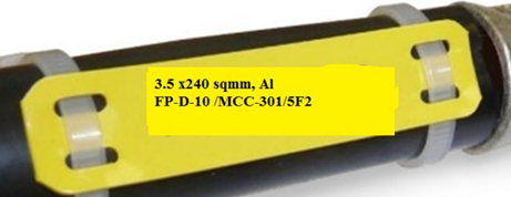
The cables which are inside the cabinet such as power supply, internal bus, etc. Must be labeled properly with the cable number and the cable number should be on both sides. The cable from the cabinet to cabinet also should be labeled like this. While doing the labeling it must have the destination of each cable end. The communication cable in the cabinet must be run through a PVC conduit and this must be done for the cables within the panel and also between the panel.
Cable tagging
Where should we do cable tagging?
We must do tagging where two or more control circuits are run through or to a control device, outlet box, or junction box. We must tag each circuit in a way that would be a guide in making connections.
- Cable tags must be provided inside the cubicles at the point of glanding
- It should be done at the field end termination before entry to the marshalling box/terminal box.
- Cable tagging must be done at a distance of one to two meters of the crossing of any wall, floor, etc.
- It should be done within a distance of 1 or 2 meters of either side of the acute bends and tray jumping.
Cable testing before installation
- Test the continuity of the conductor
- Check the insulation resistance between the conductor and the earth
- Determine the resistance between conductors
Cable testing after the installation
- Insulation resistance between conductors must be checked
- Check the insulation resistance between the conductor and the earth
- Termination firmness must be checked
- Check if there is any absence in cross phasing
Cable ferruling
Proper electrical connections can be achieved by ferrules during the wire termination in the terminal blocks or in other devices.
A ferrule would protect and keep together the wire strands in a screw terminal. By using ferrules, we could recognize the wire termination in equipment or in a control panel. The major purpose of the ferrules is to protect the wire, ferrules would be able to prevent the wires from breaking while bending, or in case of stress or vibrations. A ferrule can be described as a metal tube mostly made of copper which is capable to deform according to the applied force. There are different ferrule sizes and we can select the ferrule according to the wire which is to be crimped. We can select different colors for ferrules to determine the size.
Cross ferruling
Cross ferruling is done to determine the wire source and also where this wire is connected. So while doing cross ferruling the source and destination of the wire would be added to the tag. By checking this tag we would be able to determine the details about wire connections like where it is installed, terminal, polarity, etc. So in case if there is any fault then we could easily find the faulted section with the help of this.
Environmental and Safety Considerations for Panel Design
- Panel Cooling and Ventilation: Detail requirements for panel cooling, like fan specifications, air conditioning units, or heat dissipation designs in high-temperature environments.
- Ingress Protection (IP Ratings): Discuss IP ratings (like IP54, IP65) needed for panels based on environmental exposure to dust, water, or corrosive elements.
- Fire and Explosion Protection: Explain when to use explosion-proof enclosures and materials for panels in hazardous areas.
Grounding and Earthing in Automation Panels
- Importance of Grounding: Describe how grounding reduces noise and improves signal quality, especially for sensitive equipment like PLCs and DCS.
- Best Practices for Grounding: Include details on grounding types, materials, and methods for various cabinet types (e.g., marshalling vs. system cabinets).
- Testing Ground Integrity: Outline tests and inspections to verify grounding continuity and efficacy.
Cable Management in Automation Panels
- Cable Routing and Separation: Explain how to route power, communication, and signal cables to avoid interference and improve panel organization.
- Cable Bend Radius Requirements: Provide guidelines on maintaining cable integrity by adhering to minimum bend radii, especially for fiber optics and network cables.
- Using Cable Trays and Ducts: Describe organizing and securing cables within panels and across panel networks.
Labeling and Documentation for Panels
- Panel Layout Diagrams: Provide standard layouts and the purpose of having a clear, labeled diagram on or inside each panel.
- Documentation for Maintenance and Troubleshooting: Explain required documentation, such as wiring diagrams, terminal layouts, and network configurations, for quick troubleshooting.
Maintenance and Inspection of Automation Panels
- Panel Cleaning and Care: Describe safe cleaning techniques to maintain panel integrity and avoid dust buildup, which can cause overheating.
- Routine Inspections: List the recommended frequency and key areas to inspect in each cabinet type, including looking for loose connections, dust buildup, and corrosion.
- Testing Procedures: Outline steps for continuity tests, power integrity checks, and verification of communication links.
FAQ in Automation Panels
What are the different types of automation panels?
Automation panels come in several types, each designed for specific functions in industrial automation:
- Programmable Logic Controller (PLC) Panels: Used for controlling machines and processes.
- Distributed Control System (DCS) Panels: Designed for complex process control, especially in large plants.
- Human-Machine Interface (HMI) Panels: Allow operators to monitor and interact with the automation system.
- Motor Control Centers (MCC): Manage and control electric motors.
- Remote I/O Panels: Extend I/O capabilities of central control systems by placing I/O close to field devices.
- Variable Frequency Drive (VFD) Panels: Control the speed of electric motors by varying frequency and voltage.
What are the different parts of automation?
Automation systems generally consist of these main components:
- Sensors: Measure process variables like temperature, pressure, and flow.
- Controllers: Such as PLCs and DCS, which process data from sensors and send commands.
- Actuators: Devices that physically control equipment, like valves and motors.
- Human-Machine Interface (HMI): Displays and control interfaces for operators.
- Communication Networks: Enable data exchange between devices and controllers (e.g., Ethernet, Modbus).
What is the automation design process?
The automation design process involves:
- Installation and Commissioning: Set up the system and ensure it works in the actual environment
- Requirements Gathering: Define objectives, scope, and specifications.
- System Design: Develop a blueprint for hardware, software, and communication setup.
- Component Selection: Choose appropriate sensors, controllers, and actuators.
- Programming and Configuration: Write control logic for PLCs and set up HMIs.
- Testing and Validation: Verify that the system meets requirements before deployment.