Table of Contents
- What does the word Fotonic means?
- What is a Fotonic sensor?
- Working principle of Fotonic Sensor
- Construction & Working of Fotonic Sensor
- How Fotonic Sensor is used to measure displacement?
- How Fotonic sensor can be used to measure at longer distance?
- Fiber-Optic Probes
- Fiber Optic Probe Configurations
- What are the limitations of sensors?
- How the Fotonic Sensors used in Surface Reflectivity measurement?
- How the Fotonic Sensors used in Pressure measurement?
What does the word Fotonic means?
- The word “Fotonic” is an acronym for “foh-ton-ik,” which refers to a photonic process.
- The fundamental unit of electromagnetic radiation; the electromagnetic energy’s quantum.
What is a Fotonic sensor?
- Position, displacement, and vibration are measured via Fotonic sensor.
- A light beam is transmitted by the Fotonic sensor via fiber-optic probe.
- The light strikes the surface in question before returning.
- An electrical signal is created when the received light’s intensity changes.
- The strength of this electrical signal is inversely related to the separation of the probe tip from the target surface.
- A sort of non-contact position, displacement, and vibration measurement sensor is the Fotonic sensor.
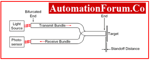
Working principle of Fotonic Sensor
- A non-contact instruments that measures displacement, vibration, and surface condition using the fiber optics lever concept.
- The Fotonic Sensor sends a laser beam through a flexible fiber-optic probe, captures light reflected off the target surface, and transforms this light into an electrical signal proportional to the measured distance between the target and the probe
- In order to identify a target surface’s position, displacement, vibration amplitude, frequency, and wave form, the fiber optic sensor’s output signal voltage is next used.
Construction & Working of Fotonic Sensor
Click below link to understand more about Construction & Working of Fotonic Sensor
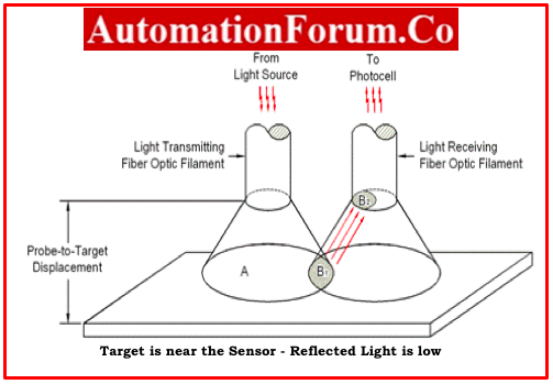
How Fotonic Sensor is used to measure displacement?
- The amount of reflected light (A) that a fiber optic probe sees when it is placed close to a target (B2) is minimal.
- Yet, the amount of light shone on the receiving fibers (B2) grows quickly as the target gets farther away from the probe.
- In this range, even little target motions result in a noticeable increase in the amount of received light.
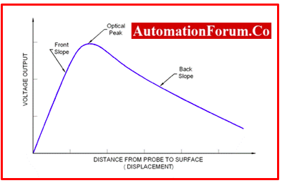
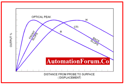
- The relationship is quite sensitive when the probe is close to the target when curve is plotted. The voltage output which is proportional to the light intensity received verses the distance between the target and sensor.
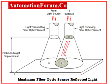
- The illuminated area (A) in gets bigger as the distance grows, increasing the quantity of reflected light that the receiving fibers can see (B2).
Fiber Optic Probe Response Curve
- The fibers are eventually accepting the greatest quantity of light possible when area B2 reaches saturation.
- The Fotonic Sensor now produces the highest voltage output possible.
- The optical peak refers to this pinnacle.
- The probe diameter and numerical aperture (N.A.) of the fibers, not the surface reflectivity, determine the displacement range over which the initial voltage rises and where the maximum output occurs.
- The output sensitivity necessary for examining and contrasting surface conditions is provided by adjusting the optical peak’s amplitude.
- Additionally, it is utilized to calibrate every fiber optic probe in order to replicate the MTII-established sensitivity factors.
- The front slope of the performance curve shown in above response curve refers to this extremely sensitive region.
- Three distinct reflective surfaces are depicted in below figure.
Fiber Optic Probe Response Curves to Different Target Reflectance
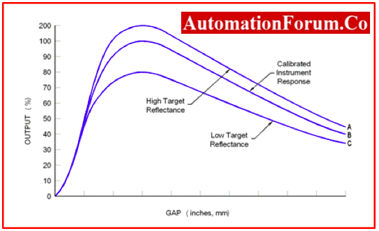
- Curve A: Instrument response curve in the case of a high target reflectance.
- Curve B: Instrument response curve with a calibration
- Curve C: if the desired reflectance is low, the instrument response curve
For all three samples, the optical peak happens at the same operating distance.
- The front slope and back slopes can be duplicated by changing the amplitude of this peak to correspond to the amplitude specified during the calibration procedure (Curve B).
- The sensors plug-in module’s memory stores this slope’s or sensitivity value, which is then utilized to translate voltage into a displacement or position.
- The light intensity can be adjusted even more if a higher level of sensitivity is necessary.
For instance, a 20X increase in lamp intensity corresponds to a 20X increase in the sensitivity of the fiber optic probe.
- Electronic circuitry that uses a silicon photodiode to detect lamp intensity can easily achieve this.
- A wide range of sensitivities can be chosen entirely by electronic control because the silicon photodiode is linear over several orders of magnitude of light intensity.
- A reliable displacement reading can be obtained by using an electronic servo control to maintain a constant lamp intensity by using the lamp monitor photodiode as well.
- Continued target movement away from the probe results in a reduction in the voltage output and a loss of the intensity of the reflected light as seen by the receiving fiber (B2) .
- Each module holds the front and back slope’s sensitivity factor, giving each fiber optic sensor two separate operating areas.
- There are two extremely sensitive areas
- With a tiny standoff and measurement range
- With a greater standoff and measurement range.
How Fotonic sensor can be used to measure at longer distance?
- By using Optical Extender, the Fotonic Sensor can also function at longer standoff distances.
- In doing so, the fiber optic probe’s light is focused to a position that is roughly 0.32 inches (8mm) beyond the front of the lens that is furthest to the camera.
- An image of the probe face will appear on the surface of the reflecting target when the distance from the front is roughly equal to the focal length of the lens assembly.
- Less light is projected onto the receiving fibers since the returning light enters the transmitting fibres.
- The below response curve illustrates how the instrument’s output signal abruptly nulls out when the amount of light decreases.
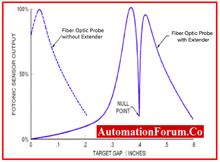
Fiber Optic Probe Extender Response Curve Compared to Standard Probe
- The image becomes distorted and the returning light starts to enter the receive fibers once more when the target distance is moved significantly away from the focal point in either direction.
- A peak in the output signal results from this activity on either side of the null.
- With the exception of the standoff distance, which is now on the order of 100 times greater than before, the displacement/output relationship will be similar to that which would have been obtained with the same probe staring directly at the reflecting surface.
- Some Optical Extender versions are designed to have a magnification factor to achieve even higher sensitivity while preserving the benefit of a larger working gap.
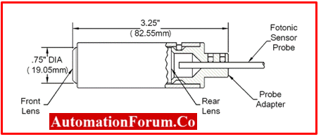
Fiber-Optic Probes
- The flexible fiber optic probe, which is made up of two sets of fiber optic filaments jacketed into one, is the main component of the Fotonic Sensor.
- Active diameters can reach 0.007 inches (0.177 mm), which makes them perfect for measuring small targets.
- Three common fibre optic probe configurations to offer a wide range of sensitivities and measurement ranges.
- Random Fiber DistributionHemispherical Fiber Distribution
- Concentric Fiber
- The distribution of the transmitting and receiving fiber optic filaments in the probe tip determines these configurations.
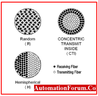
Fiber Optic Probe Configurations
Random Fibre Distribution
- A random combination of the transmitting and receiving fibers is referred to as a random fiber distribution.
- Because of the close interaction between neighbouring fibers, fibre optic sensors with random fiber patterns exhibit high displacement sensitivity but have a limited measuring range.
Hemispherical Fiber Distribution
- The transmitting and receiving fibers are divided into two distinct groups by a hemispherical fibre distribution, with the sending fibers making up half of the probe tip and the receiving fibers the other half.
- Although they have a large range, hemispherical probe tips have a low displacement sensitivity.
Concentric Fibre Distribution
- A concentric group of receiving fibers surrounds a group of transmitting fibers at the probe tip in a concentric transmit inside fibre distribution.
- This fibre optic probe design provides a middle ground between the long-range/low-sensitivity hemispherical probe fibers and the high-sensitivity/ short-range random probe fibers.
- This type of probe is less sensitive to targets that are tilted because of their symmetrical configuration.
The relative performance of the various fiber optic configurations is shown in below figure
What are the limitations of sensors?
- When the distance between the Fotonic sensor and target exceeds the diameter of the tip of the Fotonic sensor, there are restrictions in the measurement of characteristics like displacement, position, or vibration.
How the Fotonic Sensors used in Surface Reflectivity measurement?
- Changes in surface reflectivity and/or changes in light transmission through a medium can both be seen with the fotonic Sensor.
- Applications such as surface finish comparison and surface fault identification can benefit from this.
How the Fotonic Sensors used in Pressure measurement?
- In applications where changing pressure changes a target’s position or reflectance, fiber optic sensors can also be used to detect pressure.
- Fiber optic sensors are ideally suited for transducers and high frequency applications due to their non-contact and no-hysteresis properties.
- Fiber-optic sensors can function in almost any gaseous or liquid medium.
- The Fotonic Sensor can be utilized in pressure/vacuum applications by adding vacuum or pressure bushings along the fiber optic probe bundle or even on the probe tip itself.