Table of Contents
- What is a Control Valve?
- Control Valve vs Mechanical valve
- Control Valve Requirement
- Basic Parts of Control Valves
- Roles of Control Valve
- Examples of control valve
- Actuator & Body in Control valve
- Function of Actuator
- Types of Actuator
- How actuator controls the rate of fluid flow?
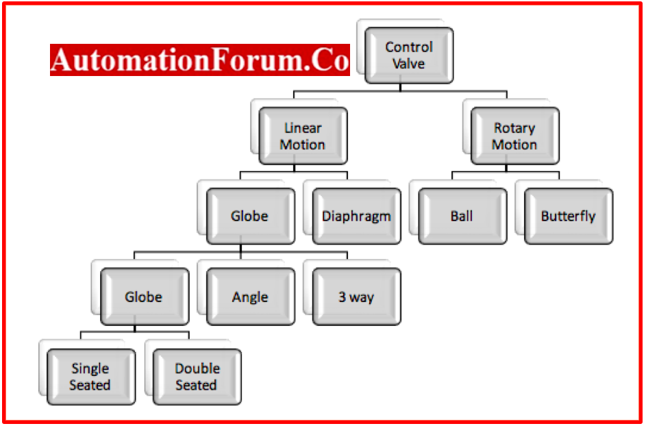
- Category of Valves
- Types of control valve
- What are the commonly used Flow Control Valve
What is a Control Valve?
The control valve regulates a flowing fluid, such as gas, steam, water or chemical compounds, to take into account the disturbance caused by the load and to keep the controlled process variable as close to the goal set point as is practically possible.
Control Valve vs Mechanical valve
- The operator will control mechanical valves in the field, but control valvecan be controlled from a distance.
- Control Valves will go through the fail safe condition when needed, while mechanical valves won’t be able to do (Fail Open or Fail Close).
- When Control Valves are used in a process system, the operator will need to do less work because the parameters (Flow, Level, and Pressure) will stay the same on their own.
Control Valve Requirement
- Have sufficient capacity for the required service;
- Have the fluid contained without external leakage.
- Be able to endure the process’s corrosive, erosive, and thermal impacts.
- Make sure the actuator’s end connections are suitable for mating with the nearby pipes and attachment mechanisms so that the actuator’s thrust can be transferred to the valve plug stem or rotary shaft.
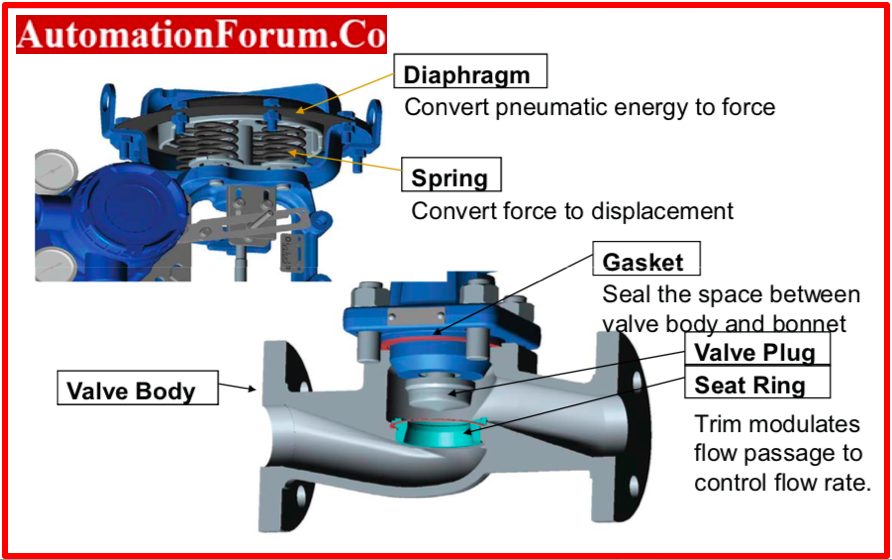
Basic Parts of Control Valves
- Actuator
- Valve body
- Positioner
Control Valve Body Parts : https://automationforum.co/control-valve-body-materials/

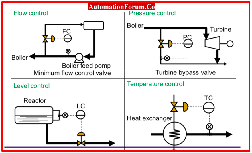
Roles of Control Valve

Flow Control Valve
- Controls flow by regulating it.
- Flow direction is determined by directional flow.
Pressure Control Valve
- Pressure valve check the system pressure to be in desired level.In the event of an increase in pressure, over-pressure protection safely releases system pressure.
Temperature Control Valve
- The pressure or flow of thermal fluid in compressors, tank jackets, heating coils, or other heating equipment is controlled by temperature regulators and temperature control valves (often referred to as TCV).
Level Control Valve
- Through the use of a mechanical float that controls a small pilot valve to regulate the main valve, Level Control Valve was once used to manage the filling of tanks and vessels.
Examples of control valve
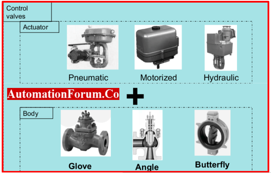
Actuator & Body in Control valve
Function of Actuator
- Position the control valve closure member
- Hold the closure member in position
- Provide Seat Load
- Provide Sufficient valve travel
- Provide adequate stroking speed
- Provide a fail mode
Types of Actuator
The basic classification of actuators are:
- Pneumatic –Based on air pressure
- Hydraulic – Based on fluid pressure
- Electric Actuator
Pneumatic Actuator
- Drive Elements are Actuators that work to exert the necessary force at the conclusion of the piston’s stroke or to create displacement as the piston moves
- The actuator group consists of a variety of rotary and linear actuators of various sizes and designs.
- The control elements, which transport the necessary amount of air to drive the actuator, complete the actuators.
Hydraulic Actuator
- An actuator is a component that activates a machine or other device.
- A hydraulic actuator’s main job is to drive a load by converting the potential energy carried by fluid pressure and flow rate into mechanical power in the form of force and velocity.
Electric Actuator
- Electric actuators are devices that use an electric motor to generate the necessary force in order to move a load or carry out activities like clamping.
- As the spindle or rotor of an electric motor rotates, rotary motion is produced.
- The drive shaft that connects the motor spindle to the electrical actuator is attached by a helical screw in its construction.
- This can rotate inside of a nut for a ball screw.
- Rotor and Stator are the two main components of every electric motor.
- The stator, a stationary permanent magnet, lies at the centre of the rotor, which is forced to feel the magnetic field it generates and begins to spin as a result.
- The two categories of electric actuators are those that move in a rotary or linear manner.
How actuator controls the rate of fluid flow?
- Keep the fluid inside without leaking to the outside;
- Have enough capacity for the intended service;
- Be able to withstand the erosive, corrosive, and temperature effects of the process;
- Have the right end connections to fit with adjacent pipelines and actuator attachment means allow actuator thrust to be transferred to the valve plug stem or rotary shaft.
Category of Valves
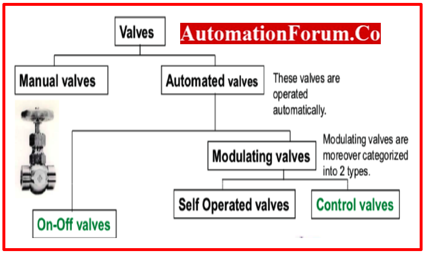
On-Off Valves
- On-Off valves simply “on” or “off” the flow.
- Let the flow medium run or stop, on the other hand.
- These valve types are primarily employed in sequential or harsh controls, such as air conditioning.
Self-operated valves
- Self-operated valves are powered by the fluid’s temperature or pressure.
- Although it is very accountable, accuracy is often not its strong suit.
Control valves
- When used with controllers and sensors, control valves operate using energy from sources such as electricity, compressed air, etc.
- Control valves and accompanying machinery achieve the most precise control.
Types of control valve
1. Ball Valves
- A bored-in route is used in the spherical plug design of ball valves.
- These valves can be controlled manually with a lever that also shows whether they are open or closed, or automatically with an actuator.
- This kind of valve allows for good liquid flow control and a safe shutoff when closed.
- They are frequently employed in paper, chemical, and sewage treatment facilities.
2. Check Valves
- These valves stop fluid flow in pipework from turning around.
- The moving fluid keeps check valves open.
- The valve will close if the flow of fluid is reversed.
- Lift checks and swing checks are included with this kind of valve.
3. Butterfly Valves
- This kind of valve is typically used in the thermal and hydroelectric power sectors, for oil and gas transmission, in water and sewage treatment facilities, and in the oil and gas processing industries.
- They are frequently used because they are portable, simple to use, self-cleaning, and there is little pressure loss across the valve when it is open.
4. Gate Valves
- When you want full flow or no flow, gate valves work best as isolating or stop valves.
- Due to the minimal flow resistance, the fluid will flow in a straight path when they are fully opened, with little pressure loss.
5. Globe Valves
- Globe valves have a special design that forces the fluid passing through to reverse direction twice.
- With wire drawing and seat erosion, they are perfect for throttling and controlling flow.
- Although they are more expensive than gate valves, they have higher flow resistance.
6. Needle Valves
- These valves provide precise flow control.
- They have a matching seat and a pointed disc with a sharp edge.
- They are often used for chemical feed control services or continuous blowoff.
7.Plug Valve
- For on-off service, plug valve is utilized. The oldest kind of valve is this one.
- Plugs can be tapered or spherical. To allow the fluid to flow, a slit has been made into the plug. With just a quarter turn, it may be opened or closed and offers a straight line.
- One or more openings can be added to a plug valve to change the flow direction. There are lubricated and non-lubricated varieties.
- Spherical plug valves are helpful for automated process control operations.
- In the oil industry, lubricated plug valves are employed, although non-lubricated valves are preferred when contamination must be avoided.
8. Angle Valve
- Angle valves result in less pipe fittings and a reduced pressure drop in the piping system.
- Corrosive fluids can be utilized with angle valves.
- Both a single body and a split body are possible.
9. Pinch valve
- It can be applied to throttling and on-off activities.
- A sleeve on the valve can be changed.
- Low pressure drop, low initial cost, and minimal maintenance costs are all advantages.
- Slurries may be handed using it.
- Its operating system is totally separate from fluid.
- By doing this, corrosion and pollution issues are resolved.
10. Diaphragm Valve
- The flexible diaphragm of a diaphragm valve is used in a “pinching” technique to stop the flow of the valve.
- Weir and straight-way are the two varieties that are offered.
- The weir-type is the more commonly found of the two.
- This is so that the straight-way type doesn’t stretch the diaphragm as much, which could reduce its lifespan.
What are the commonly used Flow Control Valve
Gate valve, Globe valve and pinch valve are the most used industrial flow control valve.Check Valve is mostly used in flow control to prevent the pressure building inside a system and to controls the backflow.
Themost used flow control valves are:
- Check Valve
- Ball Valve
- Butterfly Valve
- Gate Valve
- Globe Valve
- Needle Valve