- Types of PLC Programming Languages
- What is a Ladder Diagram (LD)?
- Key Features of Ladder Diagram:
- Basic Components of a Ladder Diagram
- Inputs and Outputs in Ladder Diagram
- Power Flow in Ladder Diagram
- Branches in Ladder Diagram (LD)
- Inputs and Outputs in PLC Programming
- Input and Output Representation in Ladder Diagram
- Input and Output Addressing in PLC Programming
- Advantages of Ladder Diagram (LD) in PLC Programming
Programmable Logic Controllers (PLCs) serve as control devices for machinery and production processes in industrial automation systems. Programming Language software suits PLC devices with Ladder Diagram (LD) serving as one of the most popular communication methods.
Types of PLC Programming Languages
The international standards published by IEC 61131-3 include five programming languages that specifically target PLC controls including:
- Ladder Diagram (LD)
- Structured Text (ST)
- Sequential Function Chart (SFC)
- Instruction List (IL)
- Function Block Diagram (FBD)
The simplicity combined with its electrical circuit diagram appearance makes Ladder Diagram (LD) stand out as the main programming language choice.
What is a Ladder Diagram (LD)?
The Ladder Diagram (LD) serves as a graphical programming language which operates specifically for PLCs under its Ladder Logic name. The programming language arranges diagrams in a visual manner to represent electrical circuits which appear similar to ladder structures.
Key Features of Ladder Diagram:
- The programming language uses graphical elements to show control logic.
- The programming language is easy to understand for experts due to its graphical format that matches electrical circuit diagrams.
- The programming language functions as a universal standard across all industries worldwide for implementing PLC software.
Basic Components of a Ladder Diagram
Rungs and Rails
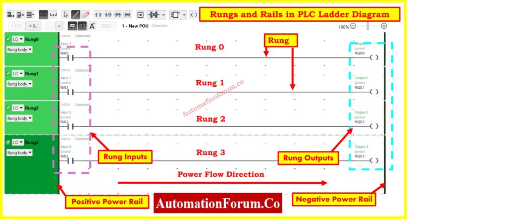
A Ladder Diagram contains two essential elements which are rungs and rails to provide its basic foundation.
- Rungs: The horizontal lines within the diagram represent the logical connections as rungs. Every rung contains both input conditions together with active output commands..
- Rails: The two vertical lines that represent power supply lines.
- Left Rail – Positive Power Rail
- Right Rail – Negative Power Rail
Refer to the attached image
The provided diagram displays four rung levels (Rung 0, Rung 1, Rung 2, and Rung 3) which connect input and output symbols along their paths between the two rails. Power flows along the diagram starting from the left side heading toward the right.
Inputs and Outputs in Ladder Diagram
- Outputs: The ladder diagram includes elements that function as devices such as motors alongside solenoids and indicator lights. The visual representation illustrates output values which include %Q0.0 and %Q0.1 and %Q0.2 followed by %Q0.3.
The image contains left side entries labeled as inputs and right side elements identified as outputs that make up each rung element.
Power Flow in Ladder Diagram
- The Positive Power Rail provides the power initiation point from its position on the left side.
- Power passes through the input devices (switches and sensors and more).
- When conditions are satisfied the system activates the output coil (relay, motor, etc).
- The power signal flows down to the Negative Power Rail through the final stage (right side).
The programming language known as Ladder Diagram (LD) provides an effective and straightforward way of working with Programmable Logic Controllers (PLCs). The system contains elements named rails and rungs which make up procedural paths for automated processes. The visual representation clearly displays all components including rungs and inputs together with outputs and power path thus providing excellent reference content about Ladder Logic.
Learn more about the Understanding Different types of Timer blocks used in a PLC ladder logic
Branches in Ladder Diagram (LD)
A Ladder Diagram implements branches to create multiple logical sections which run parallel to other structures within each rung. The main types of branches consist of three distinct categories.
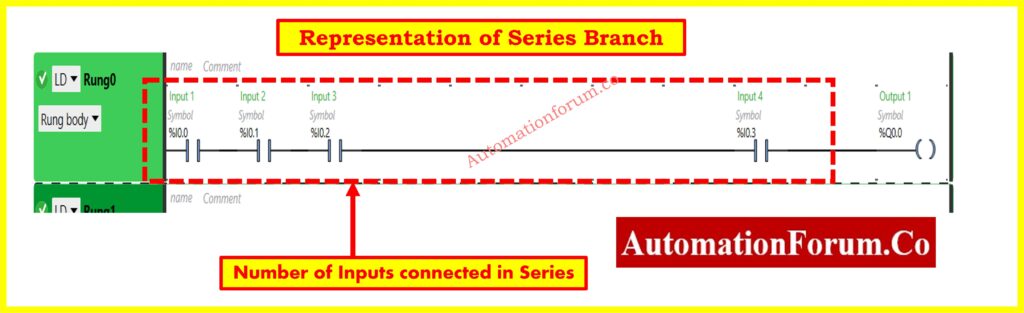
1. Series Branch
- The Series Branch structure features multiple inputs and outputs connected in sequence order inside one rung.
- For the output to activate the complete conditions must be verified by activating all required inputs.
2. Parallel Branch
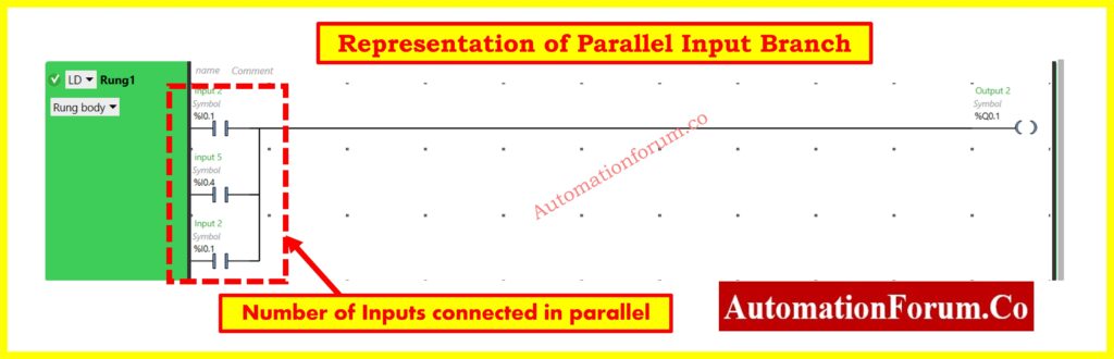
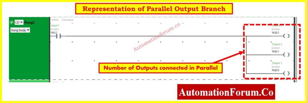
- Several inputs or outputs function alongside one another when connected in parallel through a Parallel Branch.
- Using this configuration the system will activate the output when any single condition from among the parallel inputs gets satisfied.
3. Nested Branch
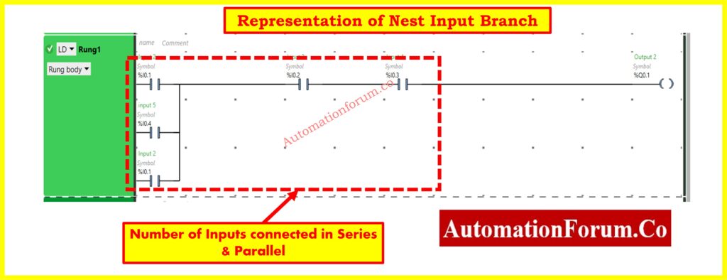
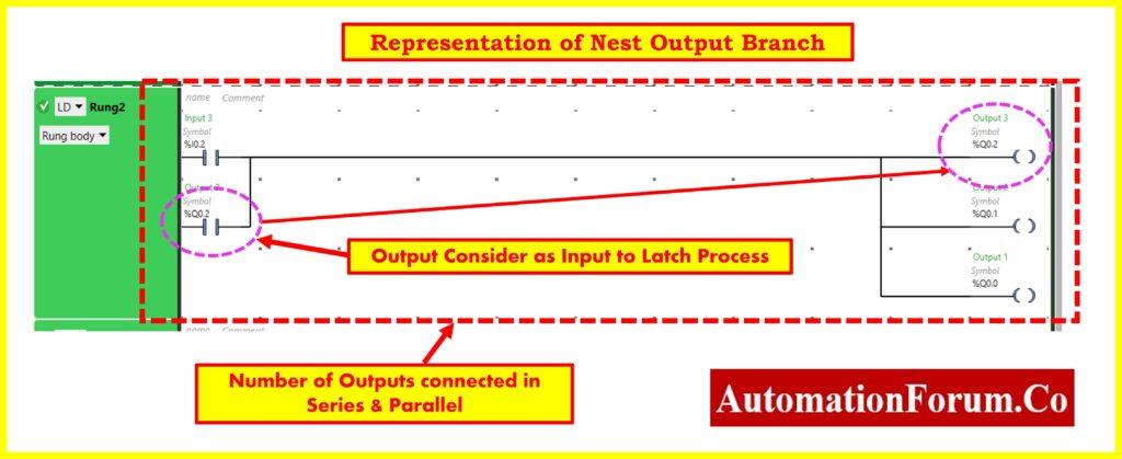
- The Nested Branch merges Series and Parallel connections into either the same rung or across multiple rungs in a control application.
- Complex logic operations benefit from this control structure since it allows sequence execution of required conditions together with alternative paths.
The branching methods allow programmers to create efficient logical control circuits in Ladder Diagram (LD) programming.
Check out this guide for a Designing 2 out of 3 Voting Logic in Control Systems: A Step-by-Step PLC Ladder Diagram Tutorial with Video
Inputs and Outputs in PLC Programming
PLC programming achieves its control logic through inputs and outputs (I/O) operations.
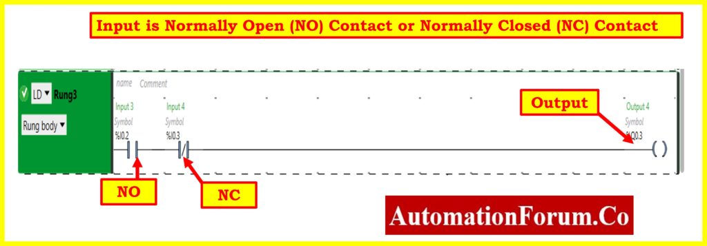
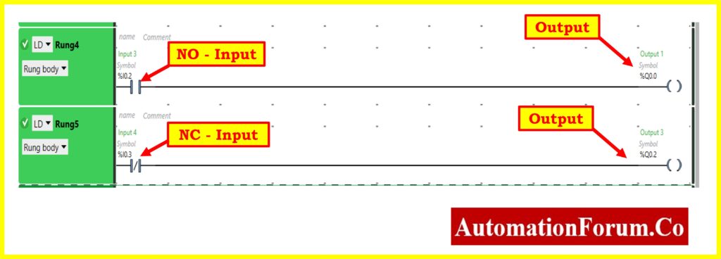
1. Inputs
- The Ladder Diagram (LD) shows this component either as a Normally Open contact or as a Normally Closed contact.
2. Outputs
- The actuators controlled by the PLC consist of coils, lamps, motors and solenoids alongside various other output devices.
- The PLC turns processed input information into output commands through the programmed logic.
- Example: A motor turning on, a warning light illuminating, or a valve opening.
Click here to learn the Step-by-Step Procedure for Creating a Ladder Diagram from Logic with Schneider Electric EcoStruxure Machine Expert Basic Software
Input and Output Representation in Ladder Diagram
The Ladder Diagram (LD) programming language uses input symbols located at the left side to connect with output symbols located at the right side. The programming model positions inputs toward left whereas outputs exist on right side.
Refer this link How to create and use different Comparator blocks in PLC ladder logic?
Input and Output Addressing in PLC Programming
The correct identification of each input and output device by the PLC depends on proper addressing during programming. Different PLC brands employ distinct device addressing configurations that programmers need to follow for program development.
Examples of Addressing in Different PLC Brands
| PLC Brand | Input Addressing | Output Addressing |
| Siemens | I0.0, I0.1, I0.2 | Q0.0, Q0.1, Q0.2 |
| Allen-Bradley | I:1/0, I:1/1, I:1/2 | O:2/0, O:2/1, O:2/2 |
| Mitsubishi | X0, X1, X2 | Y0, Y1, Y2 |
| Omron | 000.00, 000.01, 000.02 | 100.00, 100.01, 100.02 |
Every PLC manufacturer maintains a separate addressing system which requires programmers to consult specific PLC documentation for accurate program writing.
Advantages of Ladder Diagram (LD) in PLC Programming
Users find Ladder Diagram effective for its electrical relay circuit look that enables simple logic designing and reduces wiring problems. PLC programming through Ladder Diagram (LD) remains straightforward because it uses readable graphical symbols that electrical workers and engineers understand without extensive programming expertise.
LD symbols include Normally Open (NO) and Normally Closed (NC) contacts together with coils which serve unique functions to support better programming clarity. The application of LD within industrial automation brings exceptional ON/OFF control effectiveness thus enabling its use in motor controls along with conveyor belts and safety interlock systems.
Technical staff utilize graphical representations for troubleshooting purposes to speed up the process of finding system faults. Progressive PLC devices enable real-time supervision thereby easing error recognition along with system forensics procedures. The automatic power cut functionality of PLCs enhances safety operations by doing away with additional hardware switches.
Due to its user-friendly nature and broad industrial adoption Ladder Diagram maintains its status as one of the preferred languages for PLC programming.
Watch this tutorial for a Designing 2 out of 4 Voting Logic in Control Systems: A Step-by-Step PLC Ladder Diagram Tutorial with Video
 in PLC programming, including components, branches, inputs/outputs, and addressing for industrial automation.)