Working Principle of Limit Switch
- The use of limit switches that can be activated by the motion of the machine is required for the automatic operation of that machine.
- A limit switch converts the mechanical motion of the machine into an electrical signal that can be used to switch circuits.
- The operating position of the limit switch is where it transitions from its normally opened (NO) or normally closed (NC) state to its operating state.
- The release position is the point at which the contact transitions from its operating state to its normal state.
How does a Limit Switch Work?
- A standard limit switch is an electromechanical device that comprises a mechanical actuator in series with electrical contacts.
- When an object known as the target approaches and makes some physical contact with the actuator the movement of that actuator plunger causes electrical contacts within the switch to either close a normally opened circuit, or open a normally closed circuit.
- The limit switch makes or breaks an electrical connection with it.
- Mechanical limit switches are made up of a mounted actuator arm when dislocated to activate a set of electrical contacts.
- Mechanical failures are the most common type of limit switch failure.
- Limit switch controls or changes the state of an electrical switch by using the mechanical movement of the actuator plunger.
- Similar devices such as inductive proximity sensors, capacitive proximity sensors, or photoelectric sensors, can achieve the same result without touching the object.
- Limit switches, in contrast to these other types of proximity sensing devices, are thus contact sensors.
- Most limit switches operate mechanically with heavy-duty contacts capable of switching higher currents than alternative proximity sensors.
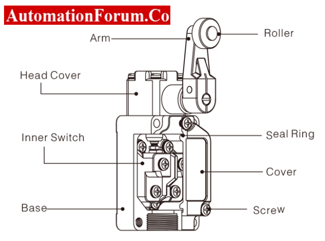
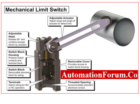
Components of a limit switch
Limit switches are made up of

- An actuator with an operating head,
- A switch body mechanism, and
- A series of electrical terminals connect the switch to the electrical circuit that it regulates.

- The operating head of the limit switch is the portion for contacting a target.
- The actuator connected to the operating head then translates the actuator’s linear, perpendicular, or rotary motion to close or open the switch.
- This actuator controls the state of the switch contact mechanism housed in the switch body.
- The electrical terminal links the switch contact to allow cables to be joined to the switch through terminal screws.
- Control switches that activate based on the movements involved in a machine’s performance are typically required for industrial machinery that undergoes automatic operations.
- The accuracy of the electrical switches must be reliable for repeated use.
- The response rate of the switch must be quick.
- Due to the mechanical specifications and performance parameters of different machines the Size, operational force, mounting method, and stroke rate are essential characteristics in the installation and maintenance of limit switches.
- The electrical rating of a limit switch should be matched to the mechanical system loads that it will be controlled in order to avoid instrument failure
Limit Switch Uses and Operation
- When a moving machine or a moving component of a machine comes into contact with an actuator or operating lever that activates the switch, the limit switch usually begins to work.
- The limit switch monitors the electrical circuit to drive the machine and its moving accessories.
- These switches can be used as pilot devices in magnetic starter control circuits to start, stop, slow down, or accelerate the functions of an electric motor.
- Limit switches are commonly used in machinery as standard control instruments or as emergency devices to prevent machinery failure.

- The vast majority of switches have either a maintained or a momentary contact.
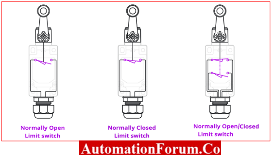
Limit Switch Contacts
- A limit switch symbol is typically included in limit switch control schematics to indicate the state of the switch contacts.
- The most common contact symbols indicate whether the limit switch contacts on the device are normally open or normally closed.
- The symbol for a “normally open held closed” contact indicates that it was wired as a normally open contact.
- When the circuit is turned off, however, a portion of the machine keeps the contact closed.
- A limit switch labeled “normally closed held open” will also have a closed wiring design but will be held open.
- Pressure and flow switches, for example, can have their contacts configured similarly.
Micro Limit Switches
- The micro limit switch, also known as a micro switch, is another type of limit switch found on control circuits.
- Because these switches are much smaller than their standard counterparts, they can be installed in places where other switches would normally be inaccessible.
- Micro switches typically have an actuating plunger that travels only a short distance to initiate the contact sequence.
- Before the micro switch will activate, the actuating plunger, which is typically located at the top of the device, must be depressed a predetermined amount.

- A small amount of movement can change the contact positions due to a spring-loading mechanism that causes movable contacts to snap between alternating positions.
- Micro switches with electrical ratings ranging from 250 volts alternating current to 10 to 15 amps can be designed with a variety of different activating arms and contacts (amps).
- Micro limit switches and sub-miniature micro switches are intended for use in applications that require compact designs and limited space availability.
- They have contact arrangements with spring-loading mechanisms similar to micro switches but are half to one-quarter the size.
- Because of their small size, these subminiature switches have contacts with electrical ratings ranging from 1 to 7 amps depending on the model.
Key Limit Switch Terminology
Several key terms are associated with designing limit switches, some of them are shown below.
- Pre Travel: The angle or distance for a limit switches actuator to travel before tripping the switch contacts.
- Point of Operation: The actuator’s position when the switch contacts are in the operating position.
- Point of No Return: The actuator’s position when the contacts return to their initial position.
- Differential: The angle or distance between the operating point and release points means between when the contacts trip and the contact reset.
- Over Travel: Any movement of the actuator component past the trip point of the switch.
- Position at the start: When no external forces are applied, this value represents the position of the switch’s actuator.
- Operating Force: The magnitude of the force (or torque for angular movement) required to move the actuator is represented by the operating force (torque).
- The minimum force of return (torque): The force (or torque for angular movement) required to return the switch actuator to its initial position.
- Total Journey: The maximum distance an actuating element can travel in a single operational cycle.
- Repeat Precision: The ability of a limit switch to repeat its characteristics during repeated (successive) operations.
What are the types of Mechanical limit switches?
Mechanical limit switches are classified as
Lever-Type Limit Switch

- A lever-type limit switch’s actuating arm is a rod connected to a lever shaft that is free to rotate when the rod is dislocated.
- A return spring returns the lever shaft to its normal state when the force- displaying rod is removed.
- The bottom of the lever shaft has a roller that rotates a rocker as it moves from right to left.
- The mechanical action, as shown in the above figure, operates one or more contacts mounted on the other side of the limit switch.
- The electrical contact may be open or closed at first. It is moved from one state to another by the action of the actuator and lever arms.
- As a result, when activated, the normally open limit switch will be closed and the closed switch will be open.
Push Type Limit Switch

The contact in the push-type limit switch shown above is operated by depressing the contact lever arm.
Classification of Limit Switch
Limit switches are categorized based on motion type
Rotary Motion Limit Switch

- It functions by rotating a shaft. When the shaft reaches a predetermined number of rotations or angles, the switch is activated.
- When the limits of travel must be adjusted frequently, rotary limit switches are preferred.
- An important application is overhead cranes for hoisting and lowering motion.
Linear Motion Limit Switch

Linear motion detects it, and contact changes are triggered. Once the limit switch is set, only minor adjustments are possible by adjusting the lever position.
Limit Switches are used for
Momentary Contact
- When the target creates contact with the actuator arm, the actuator moves from the free position to the operating position.
- At this point, the electrical contacts change their state. When the target is moved away from its point the actuating arm and contacts return to the initial state.
Maintained Contact
In some applications, the actuator and contacts stay in the same state after the movement of the target.

Some amount of force is required to return the actuator to its initial.
Advantages of Limit Switch
- High current carrying capacity
- Low price
- Familiarity with low-tech sensing.
- They are more accurate and typically have a dry contact or a contact closure that is simple to integrate into emergency stop strings or servo controlled positioning systems.
- Ideal for all industrial environments.
- Has the ability to switch loads with a high inductance.
- Capable of managing multiple loads
Disadvantages of Limit Switch
- Normal wear and tear
- Physical contact with the target is required.
- Contact bounce probabilities when compared to non-contact sensors such as proximity sensors
- Response time is slow.
- In most cases, this limitation applies to machinery that works at relatively slow speeds.
Applications of Limit Switch
- Automation of plants or machinery applications that work together.
- Limit switches are frequently used in machine tools to limit axis travel.
- In materials handling applications, this term is used to indicate the movement of material from one platform to another.
- Used in overhead cranes.
- Used to control lighting in control panels.