Wave Trapper:
A wave trap is an interference positioned on the transmission line that stops a high-frequency waveform from entering a low-frequency device. A cylindrical shape characterises the wave trap. Line trap and High-frequency stopper are some other names for wave traps (2Khz to 250Khz). We can describe the wave trap as a low pass filter or band block filter due to its ability to block high frequency. High frequency waves above 50 Hz are captured using a wave trap or line trap.
A wave trap is used to produce a high impedance to prevent high-frequency carrier waves from entering undesirable locations, usually substations. All communication in carrier wave technology is sent at a frequency between 150 kHz and 800 kHz. The parts of the power system that are intended to work at 50 or 60 Hz are damaged by this high frequency. The high voltage power system is coupled in series with an inductor coil that makes up the device.

Wave trap circuits Construction:
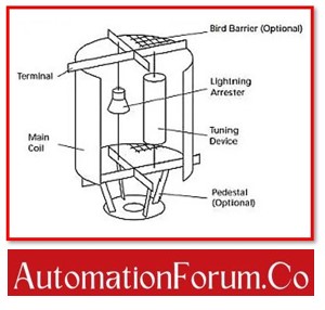
The wave trap circuit is made up of three main parts, including:
- Main Coil of Wave Trapper,
- Coupling Capacitor of Wave Trapper,
- Tuning Device of Wave Trapper and
- Protection Device of Wave Trapper.
Main Coil of Wave Trapper:
The Main Coil, which is constructed from common aluminium cable, is merely the exterior of the wave trap circuits.
If applying more than one layer is required, the layers must be separated in order to create a cooling duct between them to prevent overheating. The spacer bars used to build the cooling duct are constructed of
- Fibreglass and
- Epoxy resin.
The coil of this system’s power inductor carries the rated continuous power frequency currents. It offers the passage of electricity a low impedance path.
The trap coil is constructed by taking into consideration the total current carrying capacity of the transmission system. In high voltage transmission, the coil’s size increases.
The inductive reactance will increase as the frequency increases.

Because of this, it produces low impedance for low-frequency signals and high impedance for high-frequency signals. The high-frequency carrier signal is kept from entering the power circuits by this device.
Coupling Capacitor of Wave Trapper:
To receive a high-frequency communication signal, a coupling capacitor is utilised. As a result of the capacitor principle, a high-frequency signal has low impedance.
The impedance value decreases as the frequency increases, while the impedance value increases as the frequency decreases.

Tuning Device of Wave Trapper:
The tuning device is the following important part. The primary coil has a secure installation of this device. It is made up of
- Coils,
- Capacitors, and
- Resistors
and modifies blocking frequency or bandwidth.
The main and protective devices are linked in parallel with the tuning device. In a certain frequency band, it offers blocking impedance. It can be tuned to a single band or to several bands. The tuning circuit is protected from the elements by resin/foam-filled weatherproof casings.
Protection Device of Wave Trapper:
The protective device, which is parallel to the main coil and the tuning device, is the final major component. The protective device ensures that the tuning mechanism and main coil are protected against surge voltages. Additionally, it lowers the over-voltage levels, protecting the main coil and the tuning device.
The frequency range across which a line trap may deliver a specific minimum blocking impedance or resistance is known as its bandwidth.
Since line traps are linked in series with the power lines, the full line current can be carried by their coils. At the power frequency, a line trap’s impedance is extremely low did not result in a substantial voltage drop.
Working of Wave Trapper:

The transmission line’s two ends A wave trap is installed on both the transmitting end and the receiving end.The wave trap functions as a substantial choke coil. Only low frequency 50 Hz is permitted to the desired components.The line-trap circuit’s inductor and capacitor function as low-pass filters. The wave trap’s circuit is designed to have a high impedance path for the carrier communication frequency, which ranges from 3 kHz to 250 kHz, and a low impedance path for power frequency (50Hz).
A high inductive reactance is nothing more than an anti-frequency high impedance.
With the support of a Capacitor-Voltage Transformer, the wave trap is effectively works to route the high-frequency communication signal to the PLCC (power line carrier communication) panel.

Characteristics of Wave Trapper:
- Wave Trapper was made exclusively for outdoor use.
- Wave Trapper is comprised of dry type and air core material.
- Wave Trapper is a device with high short circuit capabilities.
- Wave Trapper is an extremely tunable equipment.
- Its self-resonance frequency is greater than 500 kHz.
Application of Wave Trapper:
In power stations, wave traps are utilised for communication.Without depending on the telecom company network, communication between different power stations is possible with Power Line Carrier Communication (PLCC) systems. In addition to speech and data communication signals, the signals are principally teleportation signals.