Clamp Meter:
A clamp meters is an instrument that measures current in an effective, practical, and secure way without the use of test leads. It was aware that the current flowing through a conductor can produce a magnetic field. Therefore, the magnetic field can be detected using this instrument, which will then give the reading of the corresponding current. These tools allow engineers to measure rapidly and extremely safely because they do not interrupt the flow of current. a clamp meter, usually called a tong tester.

Working Principle of Clamp Meter:
A clamp meter measures the magnetic induction principle to measure AC without making contact. Like any conductor, a wire generates a magnetic field as current flows through it. In order to reduce the voltage across the sensor, the Hall Effect sensor monitors the magnetic field produced by current flow. Sensor mostly detects magnetic fields forced on by low current flow.
Construction of a Clamp Meter:
The various components that can be used to construct this meter are discussed below:

1. Jaws Clamp:
Jaws clamp are employed to measure the magnetic field while the conductor’s current is flowing. It is also called transformer clamp.
2. Clamp Opening Trigger:
The clamps can be opened or shut using a clamp opening trigger.
3. Power Switch:
The meter can be turned on or off using the power switch.
4. Backlight Switch:
The LCD display’s backlight can be turned on to make it easier to read the value displayed at night or in dimly lit areas.
5. Hold Button:
The final value on the LCD panel is mostly stored by the hold button.
6. Ground or Negative Input Terminal:
The ground jack or negative of the meter cable is connected to the ground input terminal.
7. Positive Input Terminal:
The positive jack of the meter cable is connected to this terminal.
8. LCD Screen:
The measured value is displayed on the LCD screen.

9. Operable Rotary Switch:
Using this switch, the current is selected based on the range and kind of the measurement.
How Clamp Meter works?
The steps listed below can be used to utilise clamp meter.
1. Join the meter’s current probe.
2. In the region of the conductor, connect the probe’s flexible tubing.
3. The probe and conductor must be separated by a minimum of one inch (2.5 cm).
4. To the symbol, rotate the dial.
5. Verify the current value displayed on the LCD screen.

How To Use A Clamp Meter:
Without making direct touch with the instrument, a clamp meter was used to measure the current flowing through it. The measurement of extremely high currents, which could otherwise be hazardous for the operator, is made possible by the non-contact feature, which guarantees a safe working alternative. A clamp meter can also be used to check continuity, measure voltage and resistance, and some models have functions for temperature and frequency measurement as well.
Advantages of Clamp Meter:
Safety: Because there is no direct physical contact with the circuit being tested during the measurement procedure, a clamp meter ensures the safety of measuring very high AC currents.
Convenience: Since it is not necessary to turn off the circuit that carries current for measurements, circuit operation and testing can be done concurrently.
Disadvantage of Clamp Meter:
When compared to other measurement tools like a multimeter, a clamp meter’s reading accuracy is inadequate.
Types of Clamp Meter:
There are 4 different types of Clamp Meter:
- Current Transformer Clamp Meter,
- Hall Effect Clamp Meter,
- Iron vane Clamp Meter and
- Rogowski Coil Clamp Meter

1. Current Transformer Clamp Meter:
A split ring formed of ferrite or soft iron is a typical type of current clamp. A wire coil is twisted around one or both halves to create a current transformer’s single winding. The other winding is formed by the conductor it is clamped around. Like any transformer, this type only operates with AC or pulse waveforms, some of which can reach megahertz frequencies.
The primary winding used to measure current is the subject conductor, and the secondary winding is the coil.
In order to create an interference current during electromagnetic compatibility, susceptibility, testing, this type may also be utilized in reverse to inject current into the wire. The injection probe was created with this need in mind. The primary is the coil, and the secondary is the test conductor.
2. Hall Effect Clamp Meter:
The Hall effect type can measure both AC and DC, in certain cases up to the kilohertz (thousands of hertz) range. It is more sensitive. This type was frequently used in conjunction with oscilloscopes and expensive computerised digital multimeters, but they are increasingly being employed for more general purposes.
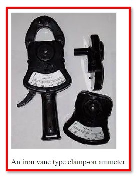
3. Iron vane Clamp Meter:
The iron vane type provides an accurate root mean square (RMS) value for non-sinusoidal AC waveforms because the magnetic flux in the core directly impacts a moving iron vane, allowing for the measurement of both AC and DC. It can only typically transmit power at frequencies up to about 100 Hz due to its physical size.
The vane is often permanently attached to the clamp meter’s analogue (moving pointer) display mechanism. It is obvious that the instrument’s calibration is not linear.
4. Rogowski Coil Clamp Meter:
The Rogowski coil current sensor resembles like and works like a current clamp. Clamp meter and power monitoring loggers both make use of this transformer without a core. It benefits from improved linearity, the absence of a core to saturate it, the ability to be made flexible, and the lack of a need for magnetic or electrical contact at the opening end. Before the detected values can be displayed, additional signal processing is required since the Rogowski coil produces a voltage proportional to the rate of change of current in the primary cable.
Major Uses for Clamp Meter:
The clamp meter is very important from an industrial and business perspective. The following are some common uses for the clamp metre:
- The main purpose of these digital meter is to measure extremely high currents. These meters cannot measure current more than 10A for longer than 30 seconds without becoming damaged.
- These meters are most frequently used by industrial, commercial, and residential HVAC systems.
- These are used when needed to fix accessible systems.
- Clamp meter are used by engineers and technicians to perform final circuit testing, diagnose electrical instrument repair issues, and other tasks.
- It is also utilised to supervise a beginner electrician while they install electrical equipment.
- The clamp meter is used for routine, urgent, and troubleshooting maintenance.
Can Watts be measured with a Clamp Meter?
Alternating current on active circuits is measured using a clamp meter. It expresses the current as amps. The clamp meter does not measure in Watts because Watts is the unit of power, but Ohm’s law makes it simple to calculate wattage: P=V*I or Wattage = voltage * current. As a result, 4,400 watts are used if your clamp meter detects 40 Amps on a 110 Volt circuit.
How Clamp Meter is better than a Multimeter?
Typically, a multimeter measures voltage, resistance, continuity, and occasionally low current, whereas a clamp meter is made only to measure current. Clamp meter can measure high currents, which is one of the key differences between them and multimeters. When it comes to accuracy, the multimeter is more trustworthy and exact. Both are superior in their own ways.
What a Clamp Meter is used for?
Measurement of Alternating Current (AC):
Open the jaws of the meter and clamp it around the conductor being measured for AC current. The display indicates the value of the measured current when the rotary dial is set to current mode. Take into consideration that during measuring, there is no actual physical connection between the clamp meter and the conductor.
Measuring Direct Current (DC):
Hall Effect sensors are used to monitor direct current (DC). These sensors generate a proportionate current that can be read from the display and detect the magnetic field. In the absence of any primary winding in the jaws, a DC value will be shown on the LCD by the earth’s magnetic field. Therefore, it is recommended to reset.