Step by Step procedure for Troubleshooting of I to P Convertor(Current to Pneumatic converter)
What is I to P Converter?
An I/P converter functions as a current-to-pressure transducer in industrial control systems, translating a 4- 20 mA current analog signal (I) into a 3 to 15 Psi pneumatic output (P).
This converter is crucial for converting DC current signals into proportional pneumatic pressure, enabling the control of valves, dampeners, actuators, brakes, and clutches in industrial applications.
It is worth noting that there are two main types of converters: I to P converters, which typically handle a 4-20mA signal, and E to P converters, which work with a 0-10V signal. While IP converters operate with current, EP converters function with voltage.
Safety Precautions
It is critical to ensure that all workers participating in the troubleshooting process have received extensive training and have a solid understanding of the specific I/P converter model and its associated systems.
Prioritize the use of suitable personal protective equipment (PPE), such as safety glasses and gloves, and ensure that the gear chosen is compatible with the potential hazards in the process area.
Before beginning any troubleshooting actions, it is critical to isolate the I/P converter via lockout/tagout methods, preventing unintentionally energization or pressure release during the diagnostic process inside the converter.
Take the hazardous area classifications inside the process environment into careful consideration, and use equipment that conforms with safety requirements related to potentially explosive or dangerous circumstances.
To reduce the risk of electrical short circuit, always turn off the power to the I/P converter before beginning any troubleshooting actions, and follow all approved safety protocols.
Release any leftover pneumatic pressure in the system to ensure a safe working environment and prevent unexpected releases during the inspection or disassembly of the I/P converter.
Conduct a thorough assessment of the I/P converter and its accompanying equipment, looking for apparent damage or signs of wear.
Follow the manufacturer’s directions and recommended troubleshooting techniques to the letter, consulting the technical documentation given for the specific I/P converter model.
Create clear and effective communication lines with other staff in the area, such as operators and maintenance teams, to relay information regarding ongoing troubleshooting activities.
In the event of unanticipated situations or issues during the troubleshooting process, familiarize yourself with and have quick access to emergency procedures, including protocols for emergency shutdowns.
Maintain proper ventilation in the work space to prevent the accumulation of harmful gasses or fumes, hence contributing to a safe troubleshooting environment.
Symptom 1: No Output Pressure
Problem
Possible Causes
Suggested Action
Reversed Current Polarity or Faulty Connections in input signal wires
Check wiring and signal continuity with millimeter.
Repair if faulty.
Broken Internal Wiring
Check instrument resistance with ohmmeter.
Correct as needed. Replace the faulty component.
No Air Supply
Ensure sufficient air supply.Isolation valve may closed.No air from the Regulator or regulator may be faulty.
Verify air supply and address any issues. Inspectand verify the the isolation valve in the instrument air line. Replace faulty regulator
Symptom 2: Maximum Output not available or not reaching
Symptom 6: Irregular Output due to PLC Signal or Faulty Output Cards
Problem
Possible Causes
Suggested Action
Fluctuating Output current signal
Inconsistent PLC signal.
Verify and stabilize the signal from the PLC.
No Output Signal from PLC
PLC signal not reaching the I/P converter.
Check PLC programming and connections.
Incorrect Output Scaling
Mismatch between PLC output scaling and I/P converter input requirements.(4 – 20mA)
Adjust scaling parameters in the AO card of PLC.
Faulty analog Output Cards in Control System
Malfunctioning output cards in the control system.
Diagnose and replace faulty output cards.
Symptom 7: Problem with Signal Isolator or Analog Junction Box Issues
Problem
Possible Causes
Suggested Action
Inconsistent Signal Transmission
Faulty signal isolator or fault in the connections
Inspect isolator or junction box for issues.
Signal Interference
External electromagnetic interference.
Shield or relocate the signal cables.
Broken Wiring Connections
Disconnected or damaged wires in the junction box.
Check and repair wiring connections.
Voltage Drops or Spikes
Power supply issues affecting the isolator.
Verify the stability the power supply to the isolator.
Symptom 8: Signal Oscillation due to PID Parameter in Control Loop
Problem
Possible Causes
Suggested Action
Oscillations in Output
Incorrect PID parameters.
Reevaluate and retune PID parameters.
Slow Response
Proportional, integral, or derivative values that are not ideal.
Adjust PID parameters for desired response.
Overreactions or Instability in the output.
Aggressive PID settings.
Fine-tune PID parameters for stability.
Symptom 9: Environmental Problems
Problem
Possible Causes
Suggested Action
Temperature Fluctuations
Ambient temperature changes affecting the I/P converter.
Install environmental controls or shielding.
Humidity or Moisture Issues
High humidity causing condensation or moisture ingress.
Seal or protect equipment against humidity.
Corrosion
Exposure to corrosive substances.
Implement corrosion-resistant control measures.
Vibration or Mechanical Stress
Vibrations impacting I/P converter stability.
Install vibration dampening or isolation. Otherwise relocate the i to p converter.
Step-by-Step procedure for Cleaning of I to P Convertor Orifice:
Cleaning the orifice of an I/P (current-to-pressure) transducer is crucial for maintaining accurate pressure regulation. Here’s a step-by-step guide on how to clean the orifice:
Materials Needed:
Screwdriver set
Gauge pin or thin wire
Step-by-Step procedure
Before starting any maintenance, turn off the supply air to the I/P transducer to ensure safety.
The orifice screw is typically located on the body of the I/P transducer and it can be found on the face of the unit below one of the calibration screws.
Use a suitable screwdriver to carefully remove the orifice screw from the unit. Inspect the screw for any visible build-up or dust.
Remove any present build-up on the screw. It’s essential to have a clear path for air flow.
You will notice a very small hole on the side of the screw. This is the orifice.
Use a gauge pin or thin wire to carefully run through the orifice hole. This helps clear any internal blockages that may be affecting the pressure regulation.
Once the orifice is cleared, carefully reinstall the screw into the side of the unit. Ensure that it fits snugly but avoid over-torquing to prevent damage.
If air is leaking past the screw when supply air is reconnected, tighten the orifice screw further until the leak stops. Be caution to avoid over-tightening.
Refer to the instruction manual for troubleshooting instructions if you run into more problems or if erratic functionality persists.
By following these steps, you may keep your I/P transducer’s orifice clear, allowing for constant and accurate pressure adjustment. This type of regular maintenance will add to the unit’s optimal performance and reliability.
Cleaning an I/P Transducer with Flapper Nozzle
If you’re dealing with a flapper nozzle type I/P (current-to-pressure) converter, the cleaning process involves some additional considerations.
Step-by-Step procedure for maintenance of Flapper Nozzle assembly
Before starting any maintenance activities, turn off the supply air to the I/P transducer to ensure safety.
Flapper nozzle type I/P converters have a flapper mechanism instead of a traditional orifice. Locate the flapper nozzle on the unit.
Depending on the model, you may need to remove the cover of the I/P transducer to access the flapper mechanism. Use a suitable screwdriver to carefully remove the cover.
Inspect the flapper mechanism for any visible blockage, debris, or obstruction. Use a soft brush or compressed air to gently clean the flapper and surrounding area.
If the flapper nozzle has any visible blockages, use a gauge pin or thin wire to carefully clear them.Make sure there are no obstructions in the way of the flapper’s movement.
After cleaning the flapper mechanism and nozzle, carefully reassemble the unit. Ensure that all components are properly aligned and secured.
If you removed the cover, reinstall it properly using the screwdriver.
Turn on the supply air to the I/P transducer and check its performance. Check for any signs of improper output or unexpected pressure output(calibration error).
If the output is not within the expected range, refer to the unit’s manual for instructions on adjusting the flapper mechanism or other calibration settings.
If you encounter persistent issues or need further guidance, refer to the instruction manual for troubleshooting specifics related to the flapper nozzle type I/P converter.
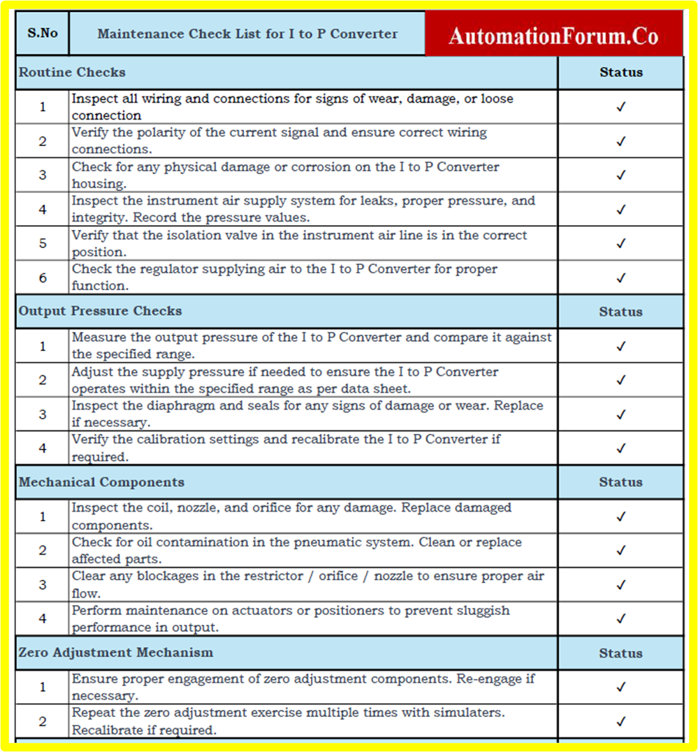
Checklist For Troubleshooting Maintenance of I to P Converter
Refer below link for the downloadable checklist for troubleshooting maintenance of I to P Converter.


 to Standard Cubic Feet per Minute (SCFM)")


 to Kg/cm² Pressure Unit Conversion Calculator")

