- One-Shot Instruction
- Example of DIFU /One Shot Instruction
- List few application of One shot instruction.
- One Shot (ONS) Instruction Input and output response
- Types of One shot
- One Shot Rising (OSR)
- PLC programming OSR
- PLC Ladder Logic Explanation
- One Shot Falling (OSF)
- PLC Ladder Logic Explanation
- What type of data are allowed for ONS?
- What are the important points to be noted while using ONS instruction?
One-Shot Instruction
- One-shots are used to produce effects for a duration of ONE SCAN ONLY. In this case, there are two types of one-shots: one that responds to the reverse transition (from on to off), and another from off to on
- One shots are excellent for catching particular events and running time-sensitive code, according to the programmer.
- This instruction is most frequently used in conjunction with more complex instructions that need us to perform certain actions just once.
One Shot is also known as
- DIFU / DIFD (Differentiate Up/Down),
- SOTU/SOTD (Single Output Up/Down),
- OSR / OSF (One-Shot Rising) and (One-Shot Falling)
- Leading edge contact/ Trailing edge contact
Example of DIFU /One Shot Instruction
- Every time an action takes place a flip/flop, flips that thing around. In this case, we’ll only utilise one pushbutton switch.
- We want an output to turn on the first time the operator pushes it up until the moment the operator presses the button again, it will be “latched” on. The output stops when he does.
- It activates at input 0000’s rising edge and output becomes true. In other words, the “DIFU” command is true when input 0000 initially goes on (becomes true). The leading or rising edge refers to the moment when an input first becomes true.
- The trailing or falling edge is what is referred to when something initially shuts off (becomes false).

Rung 1: When input 0000, which is normally open, becomes true, DIFU 1000 also becomes true.
Rung 2:NO 1000 is true, NC 1000 becomes false, and NC 1001 is still true. We have a true path, hence the statement (NO 1000 & NC 1001) OUT 1001 is true.
Rung 3: NO 1001 is true, and as a result, OUT 500 becomes true.

Next Scan
Rung 1:NO 0000is still true. Now, DIFU 1000 is false. This is so because only one scan is enabled by the DIFU instruction. (Or, the logical rung’s leading edge rising before it)
Rung 2:NC 1000 and NC 1001 are still true, NO 1000 is false. It still have a true path, hence the station (NO 1001 & NC 1000) OUT 1001 is still true.
Rung 3:Because NO 1001 is true, OUT 500 is still true.

NO 0000 stops after 100 scans (becomes false). The logic is still in the “next scan” state, as seen above. (Since DIFU doesn’t respond, the logic on Rungs 2 and 3 remains the same.) NO 0000 comes back on during scan 101.
As a result,
Rung 1: When input 0000, which is normally open, becomes true, DIFU 1000 also becomes true.
Rung 2: NC 1001 and NC 1000 both become false while NO 1000 and NO 1001 remain true. We no longer possess a true way, hence OUT 1001 is now false.
Rung 3: NO 1001 is false on Rung 3, making OUT 500 false.

List few application of One shot instruction.
• Counter application;
• Specific event capture, like conveyor timing;
• Application in flip-flops
One Shot (ONS) Instruction Input and output response
- On a successful edge detection, the one-shot instructions (ONS) produce a true signal. This means that even if the input remains true, the one-shot instruction will still be executed once for a PLC scan through the rungs. Till there is a change in positive edge direction, the output remains as constant.

Types of One shot
- One shots go by a variety of names and symbols depending on the PLC manufacturer, but they all function the same.
- The rising or lowering edge of the signal can produce a one shot.
- One Shot Rising (OSR), Positive Differential (PD), and Differential Up (DIFU) are some names given to rising edge signals.
- One Shot Falling (OSF), Negative Differential (N), and Differential Down (DIFD) are the comparable terminology for signals on the falling edge.
One Shot Rising (OSR)
Definition
- The OSR instruction is a persistent input instruction that causes a single occurrence of an event.
- When an event must begin depending on the rung changing from false to true, use the OSR instruction.
- The OSR instruction conditions the rung so that the output goes true for one scan when the input instruction changes from false to true.
- Until the input transitions from false to true again, the output goes false and stays false for further scans.
Symbol

Storage Bit
- The bit that stores the state of the output bit for the OSR instruction is known as the storage bit.
- To keep track of the OSR’s state, the storage bit is used.
- For each PLC scan cycle, it retains the signal’s most recent condition.
- It indicates that the instructions before the OSR are true and is very similar to the EN enable bit of a timer and counter.
Output Bit
- In accordance with the storage bit, the output is either set to true or false. This bit has many ladder-rung logic operations that can be applied to it.
PLC programming OSR

PLC Ladder Logic Explanation
- The OSR One Shot Rising bit is used in Rungs 3 and 4.
- The Red Light can be activated by pressing the red push Button once.
- The red Light can be turned off by pressing the red Button once more.
- When the instructions before the instruction are true, the output bit is set for one scan. It’s critical to comprehend the timing of this one scan. On Rung 3, the bit will be set to true. It will remain true until Rung 3 is reached again, at which point it will switch off.
One Shot Falling (OSF)
Definition
The OSF instruction, also referred to as One Shot Falling, enables a programmer to design a scenario in which an output is activated for a single scan if a change from a logic HIGH to a logic LOW is detected on the instruction’s input side.
Symbol
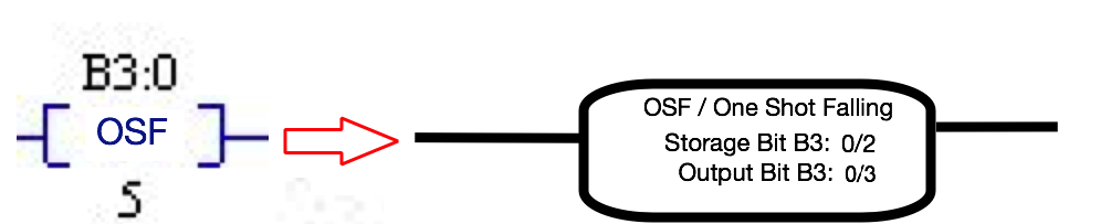
Storage bit
- To keep track of the OSF’s state, utilize the storage bit.
- It indicates that the instructions before the OSF are true and is very similar to the EN enable bit of a timer and counter.
- Usually, the program doesn’t address this instruction.
- Take into account that this is EXACTLY LIKE the OSR. Only the Output bit has a different purpose.
Output bit
When the instructions before the instruction are FALSE, the output bit is set for one scan.

PLC Ladder Logic Explanation
What type of data are allowed for ONS?
InRSLogix 500, the ONS instruction work with Boolean data, but it does not evaluate the bit attached to it.
What are the important points to be noted while using ONS instruction?
- The ONS instruction needs a Boolean bit that is not an input to work. There should be no other use of this bit in the application.
- When an instantaneous execution is necessary, the ONS instruction should only be utilized. When combined with OTL (Output Latch) and OUT (Output Unlatch) instructions, it shouldn’t be utilized to generate loops that can be avoided and made easier using other instructions.