- What is a Time Relay?
- What is the need of Time delay relay and where it is used?
- Working of Time delay relay
- Classifications of Time Delay Relay
- Based upon ON & OFF delay Time Relay Contacts
- ON Delay Timer
- Timing Diagram of ON delay Timer
- OFF Delay Timer
- Timing Diagram for an OFF delay timer
- Selection Criteria in Time Delay Relay
- Instructions for Using the Timer Relay
- Considerations for Utilizing Time Relays
- Application of Time delay Relay in Industrial Control Circuit
- What is meant by “Watchdog” timer relay?
What is a Time Relay?
A time relay is an automatic control electrical device that delays the closing or opening of connections using the principles of electromagnetic or mechanical action. It’s distinctive feature is the delay between the time the attracting coil receives the signal and the contact’s activity. To alter its delay time, the time relay’s delay performance can be adjusted within design
- Time relays are crucial to electrical control systems. Time relays control delay in various control systems. The attracting coil receives the signal before the contact acts.
- The start signal initiates timing.
- After timing, its working contact opens or closes to promote circuit work.
What is the need of Time delay relay and where it is used?
- Time relays usually start motors.
- Time delays are executive devices in simple program control.
- The most crucial control components, time relay is used extensively in remote control, telecommunication, automatic control, and other electronic equipment.
Working of Time delay relay
- When the coil is energized, the armature and pallet are drawn to the core and travel downward instantly, closing or opening the action contact.
- Nevertheless, because the piston rod’s upper end is attached to the rubber film in the air chamber, the piston rod and the lever cannot descend with the armature at the same moment.
Classifications of Time Delay Relay
Based on Working Principle
Time relays can be broken down into air damping, electric, electromagnetic, electronic, and other types according on their operating principles.
Air damping time relay
- This kind of relay is created by dampening air via the small hole.
- The electromagnetic system, the delay mechanism, and the contact make up its construction.
- The electromagnetic mechanism is a double-port direct-acting type, the contact system is a micro switch, and the delay mechanism uses an airbag damper.
Electronic time relay
- Employ the idea that the capacitor voltage in the RC circuit can’t leap and can only change gradually according to the exponential law; that is, the delay is obtained by electrical damping characteristics.
- Large delay range, good precision (usually approximately 5%), small size, shock resistance, and easy adjustment.
Electric time relay
To obtain the time delay, operate the reduction gear train with the small synchronous motor. The features are
- The delay range is vast, up to 72 hours, and the delay precision is 1%.
- Voltage and temperature don’t effect delay.
- Other time relays cannot equal its delay range and accuracy.
- Complexity size, limited life, expensive price, and power frequency effect accuracy are its drawbacks.
Electromagnetic time relay
- Utilize the principle of delayed attenuation of magnetic flux after the electromagnetic coil is shut off to delay the release of the magnetic system’s armature to achieve contact delay.
- It has a large contact capacity and control capacity.
- The delay time range is narrow, and the accuracy is slightly worse.
- It controls DC circuits.
Based upon Delay Modes
Time relays can be separated into two types: on-delay and off-delay.
- Timers are built with dials, displays, or some other sort of operator interface that is used to program the time and contact state of the device to either typically open or normally closed.
- The ON Delay Timer and OFF Delay Timer are the two most common types of timers, however there are many others and a variety of tasks they can accomplish.
ON Delay Timer
- The input signal causes the on-delay type time relay to delay immediately.
- After the delay, its execution component outputs the signal to control the circuit.
- The relay resets instantly when the input signal disappears.
OFF Delay Timer
- The off-delay type time relay is the opposite.
- After the input signal is obtained, the execution component immediately outputs a signal.
- The relay needs time to return to its pre-action state when the input signal departs.
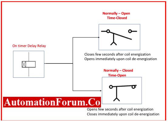
Based upon ON & OFF delay Time Relay Contacts
NOTC (normally-open, timed-closed)
- The NOTC contact is typically open when the coil is not powered.
- It is closed by energizing the relay coil, but only after the coil has been continually powered for a predetermined period of time.
- The contact moves in the same direction, whether it is closed or open, as a typical typically open contact.
- This form of contact is often open and on-delay since the delay happens in the direction that the coil is powered.
NOTO (normally-open, timed-open)
- Unlike the NOTC contact, the timed action takes place when the coil is de-energized.
- This form of contact is often open and off-delay since the delay happens when the coil is de-energized.
NCTO (normally-closed, timed-open)
- The NCTO contact is typically closed when the coil is not powered on.
- The contact is opened by energising the relay coil, but only after the coil has been continually powered for a predetermined period of time.
- The contact moves in the same closed or opened direction as a typical typically closed contact, except the opening direction moves more slowly.
NCTC (Normally Closed, Timed Closed):
- Because the coil is generally closed when it is de-energized and opened by energising the coil, the NCTC contact is identical to the NCTO contact.
ON Delay Timer
Workings of the ON Delay Timer
- The condition of the contacts that are controlled by the timer’s activation is changed by the on-delay relay timer.
- The preset time is the time that can be set or programmed into the on-delay relay timer.
- Although the preset time in an industrial control system is often set to seconds and minutes, it can range from milliseconds to hours and even days.
- The timer begins counting from zero to the pre-set time once its coil is powered; this count is referred to as the cumulative time.
- The contacts of the timer change their states when the preset time and accumulated time are equal; contacts that were ordinarily open when the coil was not electrified become closed, and contacts that were previously closed become open.
- For the same period of time as the coil is powered, the timer’s contacts will remain in their modified state.
- The timer’s accumulated time resets to zero and the contacts return to their initial condition when the power is turned off to the coil.
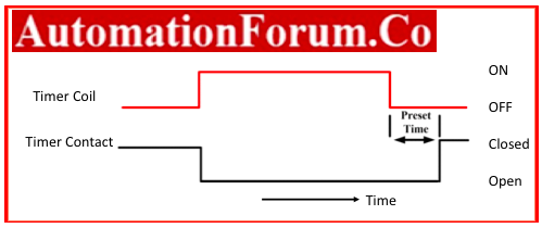
Timing Diagram of ON delay Timer
- A timing diagram is a graph that displays the state of the timer in connection to the timing device’s performance in relation to the function of the timer’s contact or output.
- The timing device’s input signal is represented by one of the two graphs in the diagram, and the timing device’s outputs or contacts are shown by colored graphic lines.
- A timing diagram uses visual lines to depict a false to true, on to off, or high to low transition.
- Because there is no in-between and values can only be off or on, the lines are formed at right angles to indicate discrete values of the time cycle.
Normally Open Timed Closed (NOTC)

- A usually open timed closed delay contact is represented by the timing diagram in Figure.
- The preset time begins to clock down as soon as the timer coil obtains electricity.
- The timer contact will change from generally closed to open whenever the total time reaches the predetermined time, and it will stay open until the timer coil loses power.
- The timer has now been reset to zero, allowing the cycle to restart.
Normally Closed Time Open (NCTO)
- The typically closed timed open contact is represented by the timing diagram in Figure.
- In this diagram, the load linked to the timer contact is on and will remain so until the timer coil is activated and the preset time equals the accumulated time.

- When that happens, the contact will open, turning off the load and keeping it off until the timer coil is de-energized.
- The timer coil will de-energize and then reset to zero, ready to cycle once more.
OFF Delay Timer
Working of the OFF Delay Timer
- Off-delay clocks are simple to recognise, just like on-delay timers.
- With the exception of the notation TD to denote time delay, the off-delay timer coil is designated the same way other loads are in ladder diagrams.
- The off-contacts Delay’s resemble single pole switches with an arrow pointing downward from the switch.
- The typically closed time close contacts are known as normally closed time open contacts, and the normally open off delay contacts are known as normally open time open contacts.
- Because the off-delay contacts are immediate, the opposite action is required.
- The contacts of the off-delay timer instantaneously change their state after the coil is powered.
- In a control circuit, the off-delay coil is activated, but counting is not initiated.
- The off-delay count does not begin until the power is cut off to the coil. When the coil is de-energized, time starts to pass. When the total time reaches the predetermined duration, the contacts of the off delay return to their initial condition.

Timing Diagram for an OFF delay timer
Normally Closed Time Close (NCTC)
- Before the timer coil is powered, the load linked to the normally closed contact will be on.
- After the timer coil is turned on, the contact will instantly open, turning off the load and keeping it off until the coil is turned off and the predetermined amount of time has passed.
Normally Open Time Open (NOTO)
- The timer coil is energized and the contact to which the load is connected is open in the normally open timed open off delay contact.
- The contact will close instantly when the timer coil is activated, turning on the load attached to the contact.
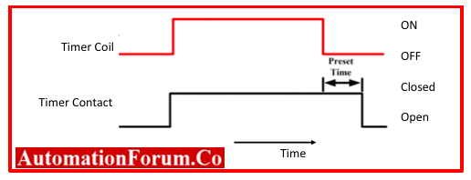
- After the timer coil has been de-energized, the load will remain on until the pre-set time equals the time that has passed, at which point it will turn off.
Selection Criteria in Time Delay Relay
- Delay mode and parameter coordination play major roles in choosing a time relay.
- Before choosing, the following factors need to be taken into account.
Choose the delay mode
- It is to be chosen in accordance with the demands of the control circuit.
- In order to prevent fault operation or even no delay, the reset time following the action is longer than the inherent action time.
- This is crucial when there are repeated delay circuits and numerous processes.
Selection Type
- When the delay accuracy is low, less expensive electromagnetic or air damping time relays are always utilised.
- Electronic time relays, on the other hand, can be employed in situations when the delay precision is great.
Choosing the Coil Voltage
- The voltage at which the relay attracts the coil is chosen based on the voltage of the control circuit.
Power supply parameter selection
- When the power supply voltage varies significantly, it is preferable to utilise electric time relays or air damping rather than transistor-style relays.
- Electric time relays shouldn’t be used when the power frequency changes.
- Moreover, air damping type should not be employed when the temperature fluctuates significantly.
Consider other factors, such as the delay mode, contact form, delay accuracy, and installation method in accordance with the control requirements, in addition to the current type and voltage level of the relay’s coil (or power supply).
Instructions for Using the Timer Relay
- Maintain a clean time relay; otherwise, the mistake will grow.
- Before using, verify that the voltage and frequency of the power source match those of the time relay.
- Choose the time relay’s control time based on the needs of the user.
- Any sort of time relay will function to fulfill the objectives of the timing control circuit as long as the timing time is identical to the predetermined time.
- For DC devices, pay attention to the polarity of the power source and the wiring in accordance with the circuit diagram.
- As soon as the time relay loses functionality, it needs to be reset in preparation for use again.
- The control circuit will be abnormal if the repeated use interval is smaller than the predetermined time.
- In addition, the power-on delay type is immediately reset after powering off, and vice versa for the power-off delay type.
- Keep it out of areas where there is obvious vibration, bright sunshine, humidity, or soil contact.
Considerations for Utilizing Time Relays
Starting point
- On the one hand, you should choose to power up the time relay when the control circuit that needs to execute timing sends the timing signal when choosing the timing point of the power-on delay time relay.
- On the other hand, when choosing the timing point of a power-off delay type time relay, you should decide to turn off the time relay’s power supply when the control circuit needs to transmit the timing signal so that the timing can be carried out.
End point
- The timing endpoint has two definitions: one relates to the moment when the set time and timing time are equal, and the other refers to the time when the contract begins to take effect.
Reset point
- The time relay must be reset in order to clear the previous timing data for the subsequent use.
- The following time it is used, if it is not reset, an anomaly will happen.
- The duration between two uses should be longer than the reset time, which is especially crucial for electric time relays.
The Relation between the timing’s Starting, Ending and Reset points
- There is a reset issue after the time relay is utilised. By the time the relay outputs, the majority of the control circuits are in the circuit at the next level. The time relay’s power supply can be turned off (power-on delay type) or powered once the timing completion signal has been precisely obtained (power-off delay type).
- The time relay’s upper and lower control circuits contain components that cannot operate simultaneously. The gadget will behave strangely if the time relay is unable to precisely operate the upper and lower control circuits at these points.
Application of Time delay Relay in Industrial Control Circuit
Flash Control Time Relay Applications
Two-time relays work together to transmit intermittent power to the light by providing consistent frequency on/off pulses of the contacts.
Purge Control for In Furnace Safety
- The fan must run for a specific amount of time to clear the furnace chamber of any explosive or dangerous steam before the combustion furnace can be properly started.
- The time relay supplies the necessary time components for the furnace control work.
Electric Soft-start Delay Control
- A huge electric engine can be started without having to switch to full power from a completely stopped position, and the voltage can be softly started with reduced inrush current.
- Delay in the Conveyor Belt Sequence
- To avoid items from building up on the moving conveyor, which may halt or move slowly, several conveyor belts must be started in reverse order (the last one is first, the first one is last).
Auto start control in Engine
- Engine auto start controls are frequently found in emergency generator-powered engines, allowing for automatic startup in the event that the main electric power fails.
- Before energizing the engine’s starting motor, some auxiliary systems (such as fuel pumps and pre-lubrication oil pumps) must be started and given a certain period of time to stabilise in order to start a large engine properly. For proper engine starting, time-delay relays help sequence these activities.
Conveyor belt sequence delay
- When several conveyor belts are used to carry material, the belts must be started in reverse order (the last one first and the first one last) to prevent material from piling up on a halted or slow-moving conveyor.
- Large belts may take some time to reach their maximum speed (especially if soft-start motor controls are used). Because of this, each conveyor typically has a time-delay circuit set up so that it has enough time to reach its maximum belt speed before the next conveyor belt feeding it begins.
What is meant by “Watchdog” timer relay?
- The “watchdog” timer is particularly helpful for computer systems.
- It is typically advised to have an automatic alarm to detect computer “lockup” if a computer is being utilized to control a crucial process (an abnormal halting of program execution due to any number of causes).
- A simple way to set up such a monitoring system is to have the computer periodically turn on and off the coil of a watchdog timer relay (which is comparable to the output of the “recycle” timer).
- The signal that the computer outputs to the watchdog relay coil will cease cycling and freeze in one of two states if the computer operation is interrupted for any reason.