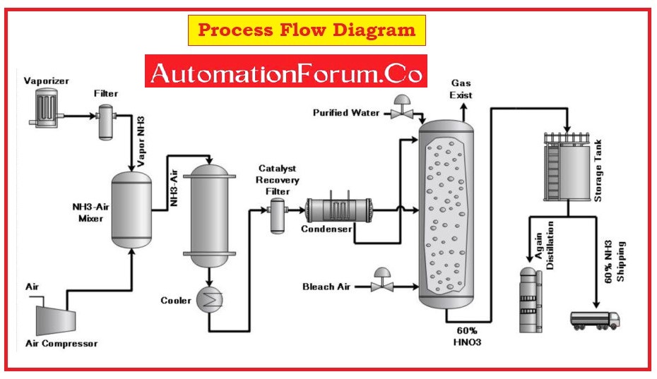
- A process Flow Diagram (PFD) is a graphical representation of the process industry that defines the relationship between major equipment, process lines, and main control loops of the process industry.
- The process flow diagram is known as a diagrammatic representation of the mass and energy balance.
- The PFD serves unit operations in a simple manner compared to P&ID
- This diagram represents the sequence of all appropriate or suitable operations that occur during a process.
- A PFD indicates the basic idea of plant design with feedstock, product, mainstream flow rates and other operating conditions.
- This PFD will not show minor details such as piping and designations.
- This diagram includes suitable information that is desired for analysis.
- This is used to make documentation of the process plant that makes it easy for the expansion of the existing plant and during the commissioning of the new plant.
- Process Flow Diagram is a dynamic document and is most often used in power plants, chemical industries, and process industries.
- This flow diagram will be stamped for release after finalizing by a concerned process engineer or project engineer.
- This will be approved for construction by the engineering group.
- This flow diagram can be updated and revised during the design phase of the project to reflect any required modifications or changes by the client.
- Frequent evaluation of relevant flow diagrams should be done on a regular basis.
- The Process flow diagram is the initial flow diagram developed during the designing stage of the project.
What are the components that are included in PFD?
Typically, the process flow diagrams for a single unit process will include the following components:
- Main process piping.
- Major mechanical equipment.
- The direction of commodity flow
- Inter connections with other systems.
- Major recirculation and bypass streams.
- Major controlling instrumentation.
- Operational data of facility components with references to a mass balance such as density, mass flow rate, pressure, temperature, etc.
- Names of the process stream.
What are the components that are not included in PFD?
Process flow diagrams generally do not include the following components:
- Pipe specifications such as pipe classes, and piping line numbers
- Details of instrumentation.
- Minor bypass lines.
- Instrumentation system.
- Controllers for controlling process parameters such as level and flow.
- Isolation and shutoff valves
- Maintenance vents and drains.
- Relief and safety valves.
- Flanges
What are the purpose and benefits of PFD?
A Process Flow Diagram has multiple purposes:
- For better understanding and control of the process standardize for optimal efficiency and repeatability.
- The purpose of this document makes it easy to train new employees for studying a process for efficiency and improvement.
- This PFD helps us to understand unnecessary steps, bottlenecks, and other plant inefficiencies.
- To model a better process or to create a new brand project.
- Communicate and collaborate with diagrams that speak to various roles in the organization or outside of it.
- A PFD serves to identify the scope of the process.
- Diagramming is quick and easy with the lucid chart.
What type of information is included in PFD?
A typical PFD includes the following information:
- All process lines, utilities, and operating conditions are required for material balance and heat.
- This includes utility flow lines that are used continuously within the battery limits.
- Equipment diagrams are arranged according to their number, designations, and process flow.
- Simplified control instrumentation with reference to the control valves and similar instruments that are involved in the process.
- Major process analyzers.
- Operating conditions around major equipment
- Heat duty for every equipment of heat transfer.
- Varying the process conditions, such as flow rates, operating pressure, & temperature.
- All alternate operating conditions.
- Table of material balance.
What type of information is not included in PFD?
There is some information that are not included in PFD:
- All minor process lines and minor equipment such as block valves, and safety relief valves that are not used in normal operation.
- Elevation of equipment.
- All spare equipment.
- Heat transfer equipment, centrifugal pumps, and air compressors that are operated in parallel or in series are represented as a single unit.
- Piping information such as pipe size, pipe material, orifice plates, strainers, and classification into hot or cold insulated jacket piping.
- It doesn’t include the instruments that don’t relate to automatic and instrumentation control.
- Instrumentation tripping system because it cannot be decided at the preparation stage of PFD.
- It doesn’t include drives of rotating machinery which are essential for the control line of the process conditions.
- It doesn’t include any dimensional information on equipment used in processes such as internal diameter, height, length, and volume.
- Equipment internals may be indicated for analyzing the operating condition of the equipment in case it is necessary, but not compulsory included.
 is a type of flowchart that illustrates the relationships between major components at an industrial plant.)