
- What Is a Differential Pressure Flow Transmitter Output Calculator?
- How Does Differential Pressure Flow Measurement Work?
- What Does a DP Flow Transmitter Output Calculator Calculate?
- Differential Pressure Flow Transmitter Calculation Formulas
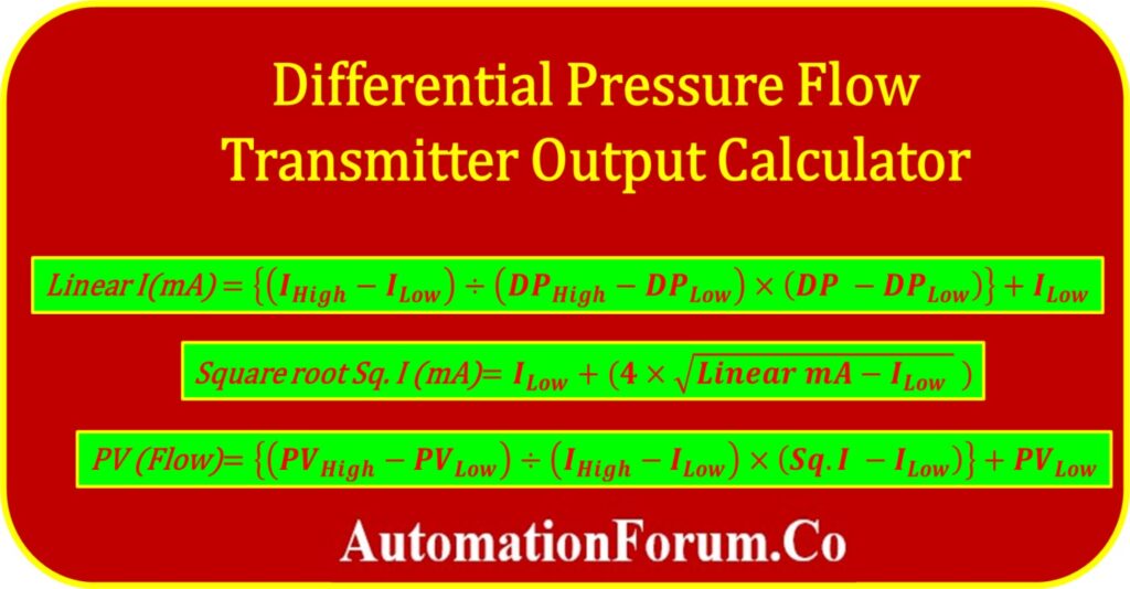
- Linear 4 to 20 mA Output Formula
- Square Root 4 to 20 mA Output Formula
- Differential Pressure to Flow Formula
- Differential Pressure and Flow Relationship
- Why Is Square Root Extraction Required?
- Significance of Differential pressure Flow Transmitter Output Calculator
- Example calculation
- Differential Pressure Flow Transmitter 4 to 20 mA Output Calculator
- Where Is Square Root Extraction Performed?
- DP Flow Transmitter 4 to 20 mA Calculation Example
- Why 12 mA Does Not Mean 50% Flow
- What Is Low Flow Cutoff in DP Flow Measurement?
- Frequently Asked Questions on Differential Pressure Flow Transmitter Output Calculator
Calculate the expected 4 to 20 mA output, square root output, and flow rate from a differential pressure flow transmitter using this online calculator. Enter the DP range, measured differential pressure, and flow range to determine the transmitter output and corresponding flow value.
This calculator is useful for instrumentation engineers, commissioning engineers, maintenance technicians, PLC programmers, DCS engineers, and process control professionals working with DP based flow measurement.
What Is a Differential Pressure Flow Transmitter Output Calculator?
A Differential Pressure (DP) Flow Transmitter Output Calculator helps engineers calculate the expected 4-20 mA transmitter output, square root output, and actual flow rate based on the measured differential pressure across a primary flow element such as an orifice plate, Venturi tube, flow nozzle, or Pitot tube.
Since the flow rate is proportional to the square root of differential pressure, the calculator automatically performs the square root conversion required for accurate flow measurement. It is widely used during transmitter calibration, commissioning, troubleshooting, DCS scaling, PLC programming, and maintenance activities.
This calculator eliminates manual calculations and helps verify whether a DP flow transmitter is producing the correct output signal for a given differential pressure.
How Does Differential Pressure Flow Measurement Work?
Differential pressure flow measurement is based on Bernoulli’s Principle. When fluid passes through a restriction such as an orifice plate, its velocity increases while pressure decreases. The pressure difference between the upstream and downstream sides of the restriction is measured by a differential pressure transmitter.
Unlike pressure, flow is not directly proportional to differential pressure. Instead, the flow rate is proportional to the square root of the measured differential pressure.
This square root relationship is why DP transmitters or control systems perform square root extraction before displaying the actual flow rate.
A DP flow measurement system normally consists of a primary flow element, impulse lines, a differential pressure transmitter, and a control system such as a DCS or PLC. The primary element creates a pressure difference, the transmitter measures the differential pressure, and square root extraction converts the DP relationship into a flow value.
What Does a DP Flow Transmitter Output Calculator Calculate?
A differential pressure flow transmitter output calculator determines the expected transmitter current and flow value from a measured differential pressure. It can calculate the linear 4 to 20 mA signal, square root extracted output, and corresponding flow rate.
In DP based flow measurement, flow is proportional to the square root of differential pressure. Therefore, square root extraction is required when converting differential pressure into a flow indication
Differential Pressure Flow Transmitter Calculation Formulas
The following equations serve as the basis for this calculator’s operation.
Linear 4 to 20 mA Output Formula
Below is the formula for determining the linear mA current output from the differential pressure of the transmitter with indicated differential pressure.

Square Root 4 to 20 mA Output Formula
A linear mA current signal can be converted into a square root output mA current signal by applying the following formula.

Differential Pressure to Flow Formula
The formula that follows determines the flow rates of the process based on the estimated square root of the mA current signal.

Where:
I High = Maximum mA output signal from the transmitter
I low = Minimum mA output signal from the transmitter
I mA = Actual linear mA current output
Sq.I (mA) = Square root mA output signal
DP High = Differential pressure high (URV) value of the transmitter
DP Low = Differential pressure low(LRV) of the transmitter
DP = Actual differential pressure(DP) indicated by the transmitter
PV high = Maximum flow rate – Upper range value scaled in the control system
PV Low = Minimum flow rate – lower range value scaled in the control system
PV Flow = Actual flow rate value shown in the control system
Differential Pressure and Flow Relationship
The relationship can be summarized as follows:
- Differential Pressure doubles → Flow increases by √2
- Differential Pressure becomes four times larger → Flow doubles
- Zero differential pressure → Zero flow
- Maximum differential pressure → Maximum calibrated flow
Understanding this relationship is essential when calibrating flow transmitters or troubleshooting abnormal flow readings.
| DP Percentage | Flow Percentage | Approximate 4 to 20 mA |
| 0% | 0% | 4.00 mA |
| 10% | 31.62% | 9.06 mA |
| 25% | 50% | 12.00 mA |
| 50% | 70.71% | 15.31 mA |
| 75% | 86.60% | 17.86 mA |
| 100% | 100% | 20.00 mA |
Why Is Square Root Extraction Required?
A DP transmitter measuring pressure does not directly measure flow. The primary flow element creates a differential pressure that varies approximately with the square of flow. Therefore, the square root of the measured DP must be taken to obtain a flow proportional signal.
Square root extraction can be performed inside the transmitter or within the PLC, DCS, or other control system depending on the system configuration.
For example:
| DP (%) | Flow (%) |
| 0 | 0 |
| 25 | 50 |
| 50 | 70.71 |
| 75 | 86.60 |
| 100 | 100 |
Without square root extraction, the indicated flow would be significantly lower than the actual flow throughout most of the operating range.
Significance of Differential pressure Flow Transmitter Output Calculator
Accuracy Verification:
- A DP flow transmitter is a critical component in flow measurement systems, and its output signal should accurately reflect the actual flow rate.
- The calculator allows technicians to compare the expected output with the measured output, enabling them to verify the accuracy of the transmitter.
- This verification process ensures that the flow measurement system is providing reliable and precise data.
Troubleshooting Assistance:
- When flow measurement discrepancies occur, the calculator serves as a valuable troubleshooting tool.
- By analyzing the expected output signal based on the measured differential pressure, technicians can identify potential issues within the system.
- It helps pinpoint whether the problem lies with the transmitter
Calibration Guidance:
- Regular calibration of DP flow transmitters is necessary to maintain accurate measurements.
- The calculator assists technicians in calibrating the transmitter by providing reference output signals for specific differential pressure ranges.
- It helps ensure that the transmitter is adjusted correctly to match the desired flow rates, enhancing the overall measurement accuracy.
Time and Cost Savings:
- The calculator streamlines maintenance and commissioning activities by providing quick and accurate calculations of the expected output signal.
- This reduces the time spent on manual calculations and minimizes errors.
- By efficiently identifying and addressing any issues, technicians can prevent costly downtime and ensure the system operates optimally.
Example calculation
You can better understand the conversion process by using the calculation in the example below.
The differential pressure transmitter has a range of 0 to 500 mBar, and it is currently showing 250 mBar. In addition, the range of the scaled flow is from 0 to 200 m3/hr. What is the expected value for the current flow rate?
I High = 20mA
I low = 4mA
DP High = 500 mBar
DP Low = 0mBar
DP = 250 mBar
PV high = 200 m3/hr
PV Low = 0 m3/hr
I mA = ?
Sq.I (mA) = ?
PV Flow = ?
Linear mA calculation
Linear I(mA) = {(IHigh – ILow) ÷ (DPHigh – DPLow) × (DP – DPLow)} + ILow
= {(20-4)÷(500-0)×(250-0)}+4
= {(16÷500)×250}+4
Linear I(mA) = 12.000 mA
Square root mA calculation
Square root Sq. I (mA) = ILow + {4 x ?(Linear mA – ILow )}
= 4+4?12-4
= 4+4?8
Square root Sq. I (mA) = 15.314 mA
Flow rate calculation
PV (Flow) = {(PVHigh – PVLow ) ÷ (IHigh – ILow) × (Sq.I – ILow)} + PVLow
= {(200-0)÷(20-4)×(15.314-4)}+0
= 200÷16×11.314
PV (Flow rate) = 141.425 m3/hr
Differential Pressure Flow Transmitter 4 to 20 mA Output Calculator
Use the following calculator to determine the flow rate, as well as the linear and square root output mA signals, based on the differential pressure that is being displayed by the differential pressure flow transmitter.
Where Is Square Root Extraction Performed?
Square root extraction can be performed at different points in a DP flow measurement loop. It may be configured inside the smart differential pressure transmitter, or it may be performed in the PLC or DCS.
The important requirement is to ensure that square root extraction is performed only once. If both the transmitter and control system apply square root extraction, the resulting flow indication will be incorrect.
| Configuration | Square Root Location |
| Smart transmitter configured for square root | Transmitter |
| Linear transmitter with DCS square root | DCS |
| Linear transmitter with PLC square root | PLC |
| External flow computer | Flow computer |
DP Flow Transmitter 4 to 20 mA Calculation Example
Consider a differential pressure transmitter with a calibrated range of 0 to 500 mbar. The corresponding flow range is 0 to 200 m³/hr, and the measured differential pressure is 250 mbar. The expected linear mA output, square root output, and flow rate can be calculated as follows.
Your existing result is:
Linear output = 12.000 mA
Square root output = 15.314 mA
Flow rate = 141.425 m³/hr
Keep these values, but fix the broken square root characters in the existing content. The current page has corrupted formula rendering such as ? characters around the square root calculation.
Why 12 mA Does Not Mean 50% Flow
For a linear DP signal, 12 mA represents 50% of the differential pressure range. However, when the DP signal represents flow through a primary element, 50% DP corresponds to approximately 70.71% flow after square root extraction.
Therefore, a DP flow transmitter with a 4 to 20 mA square root output will not have a linear relationship between differential pressure and flow.
50% DP → 70.71% Flow → approximately 15.31 mA
What Is Low Flow Cutoff in DP Flow Measurement?
At very low differential pressure, small measurement errors can create significant variation in the calculated flow because of the square root relationship. A low flow cutoff can therefore be configured in some systems to force the output to zero below a defined threshold.
The cutoff value should be selected according to the transmitter configuration, process requirements, and control system strategy. Modern DP flow calculators may include this as an optional parameter.
Frequently Asked Questions on Differential Pressure Flow Transmitter Output Calculator
Why is flow proportional to the square root of differential pressure?
According to Bernoulli’s equation, the pressure drop across a flow restriction is proportional to the square of the flow velocity. Therefore, flow is obtained by taking the square root of differential pressure.
Why is square root extraction necessary?
Square root extraction converts the linear differential pressure signal into a linear flow signal, allowing accurate flow indication and control.
Can square root extraction be performed in the transmitter?
Yes. Most modern smart DP transmitters allow square root extraction within the transmitter. It can also be performed in the PLC or DCS depending on the control strategy.
What is the normal output signal of a DP flow transmitter?
The industry standard analog output is 4–20 mA, representing the configured differential pressure or flow range.
Which primary element is most commonly used?
The orifice plate is the most widely used primary flow element because it is economical, standardized, and suitable for many industrial applications.
Can this calculator be used for steam flow?
Yes. It is suitable for steam, water, gas, air, and liquid flow measurements, provided the transmitter range and process parameters are correctly configured.
Why is my flow reading incorrect even though the DP is correct?
Possible causes include incorrect square root extraction, wrong transmitter ranging, DCS scaling errors, impulse line problems, or calibration drift.
Click here for more Instrumentation Calculators
