- What is Interposing Relay (IPR)?
- Case-I:
- Case-II:
- Working of Interposing Relay in PLC?
- Interposing Relay Interfacing with PLC Control
- Explanation of Interposing Relay with PLC (with typical wiring diagram reference)
- What are the functions of IPR?
- What is an IPR cabinet?
- Why is the IPR panel used?
- What are the Applications of Interposing Relay?
- What are the Advantages of Interposing Relay?
- Interposing Relay FAQs
- What is an Interposing Relay?
- What is the difference between interposing relay and normal relay?
- What is the full form of IPR relay?
- Why are Interposing Relays used?
- Where are Interposing Relays commonly used?
- How does an Interposing Relay work?
- What is the difference between an Interposing Relay and a Contactor?
- What is the difference between an Interposing Relay and an Interface Relay?
- What are the advantages of using Interposing Relays?
- How do you select an Interposing Relay?
What is Interposing Relay (IPR)?
- Interposing Relay is the auxiliary relay for isolating the two different systems or two different devices because these devices may have different Zero Voltage references.
- These two devices may be a Programmable Logic Controller and Contactor.
- The main purpose of interposing relay is to minimize the load on the controller relay.
- This relay allows lower control signals to switch on or switch off the load which is higher than operating capability.
Interposing Relay operation is discussed in two different cases as shown below.
Case-I:
Here in this case we are operating a PLC with a contactor with a single-phase AC supply. The PLC relay is DC type with an output voltage of 24 V. But we need a DC type interposing relay with a coil voltage of 24V DC but the contact AC type with 230 V.
The PLC operates interposing relay in the first stage & Contactor through its Auxiliary contacts.
Case-II:
The PLC relay can only avail 1A at 110 VAC, but the relay connected to the controller needs 3A at 110 VAC.
Here, an interposing relay with contacts rated for operation at 5 A at 110V AC can also be used as an interposing relay between the controller and PLC.
- Interposing relay coil requires a minimum voltage and lower current than the driving relay.
- The interposing relay contacts must handle load controller requirements
- Along with directly performing logic functions, an electromechanical relay can also be used as an interposing system between dissimilar probes, sensors, controllers, and/or control devices.
Let us consider an example of a relay used to interpose between dissimilar systems.
A fine toggle switch is used for controlling high-power lamps for an off-road automobile.
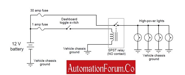
In the above-shown circuit diagram, the relay doesn’t execute any logic function but amplifies the dashboard toggle switch signal and sends that signal to the bank of high-power lamps.
A toggle switch of heavy duty is installed inside the dashboard of an automobile to make and break a lamp circuit for safety and reliability purposes.
Working of Interposing Relay in PLC?
- Interposing relays in PLC systems are used between dissimilar sensors, controllers, and/or control devices for controlling high-power circuits and the status of high-power lines.
- But dragging high power lines to the control panel is not possible because it is quite dangerous and expensive.
- Interposing relay system safeguards the PLC panel
- The Programmable Controller requires an AC supply of 120 Volts to activate but the proximity switch requires a 24V DC supply to operate which is shown below figure A.

- Interposing relay is used between switch voltage and PLC input voltage to compromise between them.
- When the proximity switch detects the object lying close to it and activates output to energize the relay coil.
- The circuit is completed for 120 VAC to reach input channel 0 on PLC when the relay contact is magnetically closed.
- A commutating diode and relay coil are used in parallel to vanish or to destroy energy stored in the coil during De-energization when the proximity switch is turned off.
- De-energization is the elimination of harmful energy from machinery equipment before switching off. A similar effect also occurs in the output circuit of PLC.
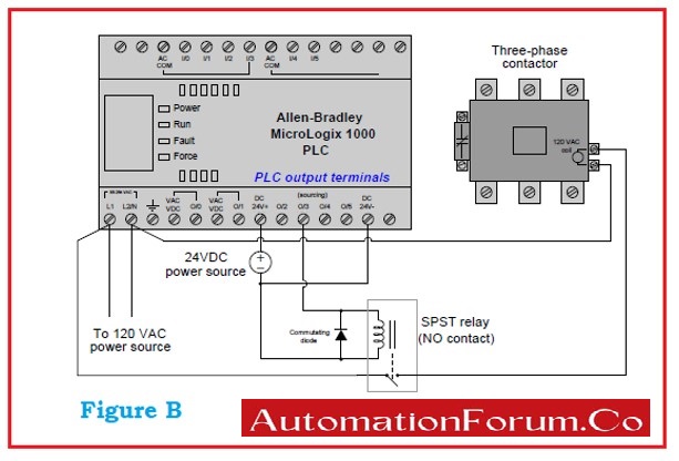
- A transistor output of PLC has the capability to handle only 24 VDC low current is insufficient for the operation of many devices.
- The circuit considered as an example shown in below figure B consists of a three-phase contactor. The coil requires an AC source of 120 V at a moderate current level for proper function.
- The relay connected interposes between the controller’s low-rated output channel and the high-rated demands of the contactor coil.
- The commutating diode is again used to destroy energy stored when the PLC is De-energized.
Interposing Relay Interfacing with PLC Control

An interposing relay is an electromechanical device used in PLC control systems to provide electrical isolation and signal compatibility between the PLC and field devices. It acts as a buffer or intermediary between the PLC output (typically a low-current digital signal) and high-power or incompatible field loads such as motor starters, solenoids, or high-voltage circuits.
PLC output modules, especially transistor or solid-state types, may not be able to directly handle inductive or high-current loads. Interposing relays solve this problem by allowing the PLC to control the relay coil with a low-voltage signal, while the relay’s contact switches the actual load circuit independently. This preserves the PLC’s lifespan and ensures safe, reliable control.
Interposing relays are also used when different voltage levels exist between the PLC and the field circuit (e.g., 24V DC PLC controlling a 120V AC load). They provide electrical isolation, preventing voltage spikes or faults from reaching the PLC’s sensitive internal circuitry.
In control panels, relays are often mounted on DIN rails and include status LEDs and socket bases for easy replacement. In summary, interposing relays enhance PLC system reliability, allow voltage and current level bridging, and simplify interface design with varied field equipment.
Explanation of Interposing Relay with PLC (with typical wiring diagram reference)

In a typical PLC control system, an interposing relay is shown wired between a PLC digital output and a field device such as a contactor coil or solenoid valve.
- PLC Output (e.g., DO1) sends a 24V DC signal when activated.
- This signal energizes the coil of the interposing relay shown in the diagram (often marked A1 and A2).
- Once energized, the relay’s contacts (e.g., NO – Normally Open) close, allowing a separate high-voltage circuit (e.g., 120V AC or 230V AC) to pass through to the field device.
- The relay contact is rated for the required load current and voltage, protecting the PLC from high inrush or inductive loads.
The image typically labels:
- PLC DO terminal ? Relay coil A1
- Common (GND) ? Relay coil A2
- Relay NO/COM ? Power line to device
This setup ensures electrical isolation, allows different voltage levels, and simplifies troubleshooting via visual relay status indication.
What are the functions of IPR?
The function of interposing relay is to separate
- Two dissimilar or non-identical systems.
- One voltage level from another.
- Energize the starter to switch on the electric motor.
What is an IPR cabinet?
Interposing Relay (IPR) cabinet is used in industrial automation systems along with automation devices for proper controlling of load circuits such as Electrical feeder contactors for motors & compressors, Air Conditioning systems, Lamps, Fans, etc. It can be used to control light circuits and AC circuits.
Why is the IPR panel used?
Interposing relay panels in industrial control are used to communicate the signals and status between the Automation system such as DCS & PLC and electrical modules in Machine control centre (MCC) such as motor control units, motors, pumps, lamps, and so on.
What are the Applications of Interposing Relay?
Interposing relays in Industrial Automation systems are used to
- To switch on or switch off any electrical drive such as such as motor driver, light driver, and contactor driver through PLC or DCS
- To turn on or turn off the heater through DCS.
- To separate low rating controllers and high rating loads in small circuits.
- Interpose between digital and analog circuits
- Interpose between low-rated control equipment and high-ratedcircuit Breaker
- To control motors and high-power lamps.
- To protect the switchgear system,
- To operate high-rated isolators, and actuators using low rated PLC system, Microcontroller, etc.
What are the Advantages of Interposing Relay?
- It provides isolation between different circuits to avoid propagation of noise from circuits and maintains safety and protection.
- It can also function as a static device for higher operational speed.
- Interposing relay governs high rated machine to run from the command issued by rated PLCs
- Interposing relay enables communication link between PLC having dissimilar voltage ratings.
- Interposing relay system safeguards the Programming Controller panel from high-intensity field current that affects the PLC system internally.
Interposing Relay FAQs
What is an Interposing Relay?
Interposing relays serve as secondary components that bridge different voltage circuits and signal types while they operate at unique levels (between AC and DC forms). The device enables electrical separation while converting signals as well as ensuring proper management of high-power loads through low-power commands. This device protects control circuits from voltage spikes and noise while enabling safe communication between PLCS and DCS and field equipment in industrial automation and motor control applications and power systems.
What is the difference between interposing relay and normal relay?
An interposing relay is used to interface PLCs with field devices, ensuring electrical isolation and voltage/current compatibility. A normal relay is a general-purpose switch that controls high-power loads using low-power signals. Interposing relays are essential when the control system cannot directly drive the field device or when isolation is needed.
They differ from protective relays, which detect faults like overcurrent or voltage issues and trigger circuit breakers to protect equipment. Control relays perform logic operations like sequencing or timing in automation circuits.
What is the full form of IPR relay?
The full form of IPR relay can refer to either Interposing Relay or Integrated Protection Relay, depending on the application and context in which the term is used.
Why are Interposing Relays used?
Interposing relays block high voltage equipment from modifying critical control signals by creating an electrical separation point. Interposing relays provide AC to DC signal conversion and they transform 24V DC control signals into 230V AC output signals. Interposing relays extend control range by enabling low-voltage PLCs or DCS outputs to manage high-voltage systems. Interposing relays create a protective barrier for sensitive control circuits while providing electrical isolation and remote control capabilities for multiple load management functions.
Where are Interposing Relays commonly used?
These components serve as interface devices that connect PLC and DCS systems to control high-power components including motors, solenoids and alarms. Interposing relays serve as safe controllers for motor starters and contactors within motor control systems. The protection of emergency stop (E-Stop) systems requires safety circuits to utilize interposing relays for creating electrical isolation barriers. You can find these relays operating in industrial lighting systems along with HVAC equipment and remote switching networks.
How does an Interposing Relay work?
The interposing relay contains two main components which include a coil together with specific contacts. A control signal of low voltage energizes the coil to cause contact opening or closure leading to high-voltage circuit control. High-power load switching operations can take place safely because control systems eliminate direct contact with hazardous voltages through this system.
What is the difference between an Interposing Relay and a Contactor?
The main utility of an interposing relay lies in controlling lower power loads within control circuits while performing voltage conversion and signal isolation procedures. Contractors exist to switch high-power electrical loads which include motors and heaters. Contactors possess higher current capacity due to their construction for continuous operation as switch components.
What is the difference between an Interposing Relay and an Interface Relay?
The two devices function as interface points yet interface relays specifically link various electronic control systems to enable their communication. The main purpose of interposing relays involves converting voltages and performing electrical isolation functions while serving industrial automation and power control systems.
What are the advantages of using Interposing Relays?
The relays establish an electrical separation barrier which protects control circuits from damage. Interposing relays make it possible for low strength PLC/DCS control signals to operate heavy loads. These devices provide voltage conversion capabilities to establish system compatibility. These devices build up reliability along with protection capabilities which decreases the probability of electrical system faults in industrial environments.
How do you select an Interposing Relay?
Selection depends on control voltage (e.g., 24V DC, 110V AC), load voltage and current, and the number of contacts required. Other factors include response time, durability, and environmental conditions (temperature, humidity, etc.). Choosing the right relay ensures efficient and safe operation in automation and power control systems.


 to Kg/cm² Pressure Unit Conversion Calculator")

