- What are SIS, PLC, and BPCS?
- What is SIS (Safety Instrumented System)?
- What is a PLC (Programmable Logic Controller)?
- What is BPCS (Basic Process Control System)?
- Difference Between SIS, PLC, and BPCS
- Why Segregate SIS from PLC and BPCS?
- How to Calculate Safety Integrity Level (SIL)
- Steps to Determine SIL
- Detailed Calculation of PFDavg
- Key Metrics in SIL Calculation
- Example SIL Calculation
- Certified vs. Proven-In-Use Devices
- Reducing Common Cause Failures
- SIS Loop Components
- Avoiding Nuisance Trips
- Communication and Diagnostics
- Why are SIS and BPCS Separated?
- Integration and Real Examples
- What is the difference between BPCS and SIS?
- What is the difference between PLC and SIS?
- What is the difference between SIS and SIF?
- Test Your Expertise in Safety Instrumented Systems (SIS)
Modern industrial automation is greatly influenced by the ideas of Safety Instrumented System (SIS), Programmable Logic Controller (PLC), and Basic Process Control System (BPCS). Although these systems are sometimes included into a plant’s infrastructure, especially in the area of safety they have several functions and follow various performance criteria.
The Safety Integrity Level (SIL) is one of the main concepts used to assess how well safety systems like SIS perform. Engineers and safety experts in charge of guaranteeing safe and effective plant operations must know how to compute SIL and how it connects to SIS, PLC, and BPCS.
What are SIS, PLC, and BPCS?
What is SIS (Safety Instrumented System)?
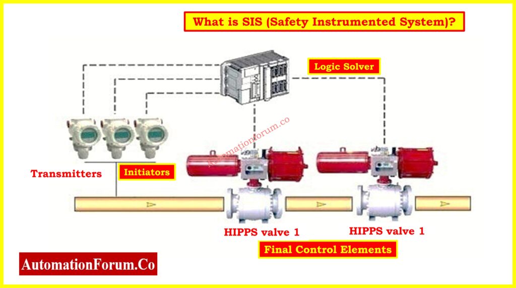
Specifically meant to monitor critical data and start corrective operations in the event of potentially hazardous circumstances, a Safety Instrumented System (SIS) is a separate system. SIS automatically provides the process back to a safe state to protect people, environment, and assets.
Understand the Standards: SIS functional safety requirements
Components of SIS:
- Devices such as gas detectors, flame, and pressure.
- Usually a safety-certified PLC, the logic solver
- Last control components like shutdown valves, solenoid valves, etc.
For instance, the SIS turns off the feed pump and opens a relief valve to prevent an explosion if a reactor’s pressure increases beyond the safe limit.
Begin with the Fundamentals: SIS (safety instrumented system) basics
What is a PLC (Programmable Logic Controller)?

A PLC, or programmable logic controller, is a digital industrial computer built for electromechanical process automation. Used for automation of electromechanical operations, a PLC is a tough industrial digital computer. These machines use control logic ladder digram , function block, structured text to automate their operations.
Key Characteristics of PLCs:
- Operates local subsystems or machines.
- Intended for discrete control uses like motors, conveyors, valves, and packing systems.
- Usually seen in smaller, independent automation systems.
- Usually part of a bigger Basic Process Control System (BPCS).
- Consists of a CPU, I/O cards, and communications interfaces.
For instance, a PLC runs a motor from a limit switch input and stops it should an overload be found.
Explore Now: Understanding PLC Racks and Chassis: Types, Differences, and Purposes
What is BPCS (Basic Process Control System)?
The Basic Process Control System (BPCS), often a Distributed Control System (DCS), is responsible for the continuous monitoring and control of complex process variables such as temperature, flow, level, and pressure.
Key Features of a BPCS:
- Monitor regular process control activities.
- Guarantees optimal, steady, seamless process performance.
- comprises advanced control methods, HMI/SCADA systems, and PID loops.
- Manages historical data logging and operator interfaces.
- Can include PLCs for subsystems.
For instance, BPCS regulates the flow rate of cooling water in a chemical reactor in order to maintain the temperature within the range that has been specified.
Quick Analogy:
- PLC = Machine Control (e.g., start/stop motors)
- BPCS = Process Control (e.g., regulate flow and temperature)
- SIS = Safety Control (e.g., shut down plant if pressure too high)
Difference Between SIS, PLC, and BPCS
| Parameter | SIS | PLC | BPCS |
| Primary Role | Safety control | Machine control | Process control |
| Purpose | Protect life, assets, and environment | Localized automation | Maintain stable process |
| Standards | IEC 61508 / IEC 61511 | IEC 61131 | ISA-88 / IEC 61512 |
| Safety Focus | High | Moderate | Low |
| Diagnostic Capability | Extensive | Basic | Moderate |
| Failure Mode | Failsafe | Varies | Unknown |
| Certification | SIL certified | Not required | Not safety-certified |
| Independence | Must be independent | Can be integrated | Integrated with PLCs |
| Examples | ESD, high-pressure shutdown | Conveyor control | Temperature control loop |
Why Segregate SIS from PLC and BPCS?
A transmitter utilized in both a control loop and a safety loop, for instance, could fail quietly and endanger both systems. SIS components are thus built and certified to high standards, with diagnostics and redundancy to avoid such situations.
Human reliability research also reveals that if they have less than one minute to act, people make the incorrect judgment 99% of the time during crises. SIS automation hence has to run without human involvement.
Prepare for Interview: Safety Instrumented System(SIS) Interview Questions and Answers
How to Calculate Safety Integrity Level (SIL)
Performance standards for each and every Safety Instrumented Function (SIF) are specified by SIL. These criteria are expressed in terms of the Probability of Failure on Demand (PFD) or the Risk Reduction Factor (RRF).

SIL Categories
| SIL Level | PFDavg Range | RRF |
| SIL 1 | ≥ 10⁻² to < 10⁻¹ | 10 – 100 |
| SIL 2 | ≥ 10⁻³ to < 10⁻² | 100 – 1000 |
| SIL 3 | ≥ 10⁻⁴ to < 10⁻³ | 1000 – 10,000 |
| SIL 4 | ≥ 10⁻⁵ to < 10⁻⁴ | 10,000 – 100,000 |
Process industries typically use SIL 4; it is particularly significant for nuclear or aerospace sectors.
Steps to Determine SIL
Perform Hazard and Risk Assessment
Using methods like HAZOP or FMEA, begin with a process hazard analysis (PHA). Identify potentially hazardous circumstances and conduct an analysis of the outcomes, probability, and the reasons why separate levels of protection are required.
Choose a SIL Determination Method
Two general techniques exist:
Qualitative Methods
- Risk Graphs
- Risk Matrices
- ALARP (As Low As Reasonably Practicable)
These are faster and easier to apply but can be subjective.
Quantitative Methods

- LOPA (Layer of Protection Analysis)
Widely acknowledged for assigning SIL in high-stakes operations, LOPA offers a numerical risk estimation.
Example: LOPA Method
A usual LOPA assesses:
- Frequency of initiating events. e.g., pump failure = 0.1/year
- Severity of consequences (e.g., poisonous release)
- Independent Protection Layers (IPLs): operator action, relief valves, alarms
- Desired risk tolerance
You decide how much further risk reduction is required and give a matching SIL.
Detailed Calculation of PFDavg
The PFDavg of a SIF is computed by:

Where:
- λDU = Dangerous undetected failure rate (failures/hour)
- T = Proof test interval (hours)
To convert failure rate in FITs (Failures In Time):
1 FIT=1 failure per 109 hours
Practical Example – Calculation of PFDavg
Let’s say:
- Dangerous Failure Rate, λD=100 FITs=100×10−9
- Proof test interval T equals one year equivalent to 8760 hours

So, your SIF achieves SIL 3 capability.
More complicated systems could have calculations including diagnostic coverage, voting logic (e.g., 1oo2, 2oo3), and device availability.
Interview Preparation: Top 25 MCQs on Safety Integrity Level (SIL) for Instrumentation and Control Engineers
Voting Architectures in Safety Instrumented Systems (SIS)
| Voting | Description | Strength |
| 1oo1 | Single device | High safety, low fault tolerance |
| 2oo2 | Two devices, both must trip | High availability |
| 2oo3 | Two out of three vote | Balanced safety and reliability |
| 1oo2D | One out of two, with diagnostics | Preferred for SIS loops |
Common voting designs employed in Safety Instrumented Systems (SIS) are summarized in the table below, which also contrasts their cost, safety performance, and usual advantages and disadvantages.
| Voting | Type | Cost | Advantages | Disadvantages |
| 1oo1 | Simplex | Low | Low cost | Prone to nuisance trips |
| 1oo2 | Dual Redundant | Medium | Safer than 1oo1 | Prone to nuisance trips |
| 1oo2D | Dual Redundant with Diagnostics | >Medium | Fault-tolerant and safe; lower cost than TMR | Higher cost than simplex and 1oo2 |
| 2oo2 | Dual Redundant | Medium | Protection against nuisance trips | Not as safe as 1oo1 |
| 2oo3 | Triple Modular Redundancy (TMR) | High | Reduces nuisance trips and improves safety; best of both (1oo2 & 2oo2) | Not as safe as 1oo2; more nuisance trips than 2oo2; expensive configuration |
In redundant architectures, voting logic changes the PFDavg formula:
- 1oo1: No redundancy
- 1oo2D: One out of two with diagnostics
- 2oo3: There is an enhancement in both availability and dependability when two out of three is used.
Refer the below link for Designing 2 out of 3 Voting Logic in Control Systems: A Step-by-Step PLC Ladder Diagram Tutorial with Video
Example for 2oo3:

Voting configurations help balance between:
- Spurious Trip Rate
- System Availability
- Risk Reduction
Key Metrics in SIL Calculation
- FIT (Failures in Time): Number of anticipated failures per billion hours.
- MTTF (Mean Time to Failure): Time anticipated before failure is MTTF (Mean Time to Failure)
- SFF (Safe Failure Fraction): Total failures’ ratio of safe + detected hazardous failures.
- Diagnostic Coverage (DC): % of dangerous failures found automatically.
Get the Basics: What is SIS (Safety Instrumentation System)?
Example SIL Calculation
If a sensor has:
- Dangerous detected failures = 20 FITs
- Dangerous undetected failures = 5 FITs
- Safe failures = 75 FITs
Then:

A high SFF is desirable for achieving higher SIL levels.
Certified vs. Proven-In-Use Devices
- Certified Devices: Have known failure rates and third-party validation (e.g., exida, TÜV).
- Proven-in-Use Devices: Trust operating history, manufacturer’s records, and field data.
Certified devices reduce SIL calculations since they arrive with known PFD and FIT values.
Reducing Common Cause Failures
To lower the possibility of systematic or common-cause failures:
- Employ various technologies, such as transmitter plus mechanical switch.
- Keep SIS and BPCS wiring and hardware physically apart.
- Select SIL-certified logical solvers including diagnostics.
- Use several architectures.
SIS Loop Components
A SIS is more than simply a controller; it comprises:
- Transmitters (e.g., pressure, level)
- Safety Logic Solver (SIL-rated PLC)
- Last Elements (e.g., shutdown valves, SOVs)
- Additional Devices (e.g., relays, splitters, solenoids)
Every part has to satisfy specified diagnostic and dependability criteria.
Start Here: What is HIPPS?
Avoiding Nuisance Trips
Nuisance trips are false shutdowns affecting production. Apply methods including:
- Voting logic
- Diagnostic alerts
- Proper proof test intervals
Redundant systems such as 1oo2D or 2oo3 strike a balance between safety and uptime.
Discover the Process: How does the HIPPS system work in the Oil and gas Industry?
Communication and Diagnostics
- Devices should be write-protected to stop unapproved modifications.
- While not required for SIS, HART/Fieldbus is beneficial for diagnostics.
- To safeguard safety logic and settings, cybersecurity is becoming more and more crucial.
Safety Integrity Level (SIL) ‘s computation and use guarantees SIS runs dependably as required. Whether you’re replacing a legacy system or developing a new plant, integrating SIS with certified components, strong diagnostics, and appropriate SIL levels is very vital for risk reduction and compliance.
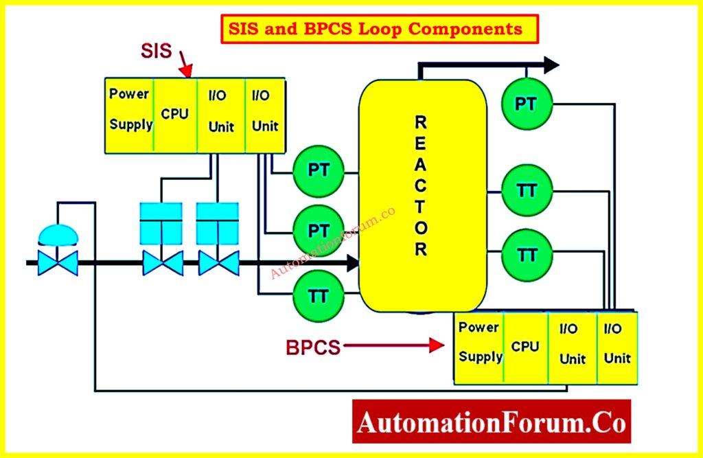
Why are SIS and BPCS Separated?

With regard to the following reasons, the separation of SIS from BPCS is absolutely essential:
- Stay clear of software flaws or power loss among other typical cause failures.
- For safety integrity, keep system independence.
- Minimize cyber security threats.
- SIS makes Management of Change (MoC) more strict.
- Avoid incidents caused by human error or defective modifications.
- Guarantees that changes in BPCS do not endanger safety logic.
Integration and Real Examples
In Power Generation:
- PLC: Used in package systems (e.g., WTP, compressors)
- BPCS: DCS system that controls the boiler, turbine, and plant balance.
- SIS: A specific ESD system designed to defend against turbine overspeed and HRSG.
Simplified View:
- PLC = Local Control
- BPCS = Continuous Process Control
- SIS = Emergency Protection
What is the difference between BPCS and SIS?

BPCS vs. SIS
| Feature | BPCS (Basic Process Control System) | SIS (Safety Instrumented System) |
| Primary Purpose | Control and optimize routine process operations. | Detect hazardous conditions and bring the process to a safe state. |
| Operation | Continuously active during normal operation. | Dormant during normal operation; acts only during emergencies. |
| Safety Role | May handle non-critical alarms or interlocks but not certified for safety. | specialized mechanism made to stop or lessen hazardous circumstances. |
| Certification | Not SIL-rated. | SIL-rated (IEC 61508 / IEC 61511 compliant). |
| Change Management | Frequent updates, flexible changes. | Strict change control with full documentation (MOC required). |
| Separation | May share devices or network with other systems. | Physically and functionally independent to prevent common-cause failures. |
While BPCS guarantees seamless process operation, the SIS is a safety layer meant to safely shut down anything should something go wrong. BPCS keeps efficiency; SIS guarantees safety.
What is the difference between PLC and SIS?
PLC vs. SIS
| Feature | PLC (Programmable Logic Controller) | SIS (Safety Instrumented System) |
| Role | Automates machines and discrete processes. | Performs safety shutdown functions. |
| Focus | Speed, flexibility, and ease of programming. | Reliability, fault-tolerance, and fail-safe operation. |
| Safety Certification | Not inherently safety-certified (unless it’s a Safety PLC). | Built using SIL-certified components. |
| Typical Use Cases | Start/stop motors, control sequences, conveyors. | Trip systems, emergency shutdowns, toxic gas detection. |
| Design Standards | IEC 61131 (general control). | IEC 61508 / IEC 61511 (functional safety). |
Used in automation, PLCs are general-purpose controllers. A PLC can be utilized in SIS if it is SIL-rated and built per safety criteria. Otherwise, SIS employs specialised safety logic solvers.
What is the difference between SIS and SIF?

SIS vs. SIF
| Feature | SIS (Safety Instrumented System) | SIF (Safety Instrumented Function) |
| Definition | A complete safety system that can include multiple safety functions. | A single safety function performed by the SIS (e.g., high-pressure shutdown). |
| Scope | System-level (hardware, software, and logic). | Function-level (specific cause-and-effect logic). |
| Components | Sensors + Logic Solver + Final Elements + System architecture. | One chain of sensor → logic → final element. |
| Example | Entire emergency shutdown system of a plant. | Closing a shutdown valve when pressure exceeds safe limit. |
While a SIF is an individual smoke detector activating a particular action, such as setting off a siren or sprinkler, the SIS is the fire alarm system in a structure.
Key Takeaways
Safe and effective plant operation depend on knowledge of the differences between SIS, PLC, and BPCS:
- PLC: Controls machines.
- BPCS: Controls processes.
- SIS: Protects life and assets during emergencies.
- BPCS is for control, SIS is for safety.
- PLC is a flexible controller, SIS must be fault-tolerant and fail-safe.
- SIS is the overall safety system; SIF is an individual protective function within it.
SIS is the overall safety system, whereas SIF is its specific protective function..
Understanding how these systems work together and independently is critical for developing safe, efficient, and standards compliant industrial processes.
Test Your Expertise in Safety Instrumented Systems (SIS)
Refer the below link to take the Quiz: Test Your Expertise in Safety Instrumented Systems (SIS): Knowledge Quiz


 to Kg/cm² Pressure Unit Conversion Calculator")

