Table of Contents
- How does self-actuated pressure control valve Work?
- Describe the types of Self-Operated Control Valves
- How to Size a Self-Actuated Pressure Regulator?
- Typical Installations for Self-Acting Pressure Reducers
- Application of Self-Actuated Valve
- Advantages of Self-Actuated Valves
- Dis-Advantages of Self-Actuated Valves
- Trouble shooting problems and its potential causes
- Problem-1: The pressure in the downstream direction increase above the adjusted set point
- Problem-2: Downstream pressure hunts
- Problem-3: Slow control response
- Problem-4: The pressure in the downstream direction fall below the adjusted set point
- Problem-5: Jerky control response
- Problem-6: Leakage at the bellows seal
- Problem-7: Color mark appears at the diaphragm rupture indicator (actuator with two diaphragms)
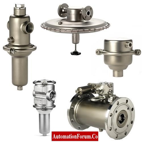
- Self-Actuated Pressure Control Valve: If outlet pressure is used to throttle the control valve then the downstream pressure is maintained at a specified set point this kind of valve is known as a self-actuated pressure control valve.
- Self-actuated pressure control valves do not use any kind of external signals to control the pressure.
- Self-operated control valve itself realizes the adjustment of various processes and other parameters.
- The name Self-actuated defines process line pressure as used as an actuating signal to open or close the pressure control valve.
- This self-actuated pressure control valve controls the pressure at both the upstream and downstream sides of the control valve.
- These valves control outlet pressure near to the desired set point irrespective of variations in inlet pressure and flow through the valve.
- Self-actuated pressure control valves maintain an adjustable pressure set-point to prescribed levels within pipelines and in storage tanks.
- Self-Actuated Pressure Control Valves are proportional type regulating valves
- The application they serve is very different from conventional safety relief valves.
- Self-actuated upstream pressure control valves: Control Valves control inlet pressure close to the desired set point opening in direct proportion to the rise in inlet pressure above the set point.
- Self-actuated downstream pressure control valves: Control Valves which control outlet pressure close to the desired set point.
- Backpressure Control Valve: If inlet pressure is used to throttle the control valve, then the upstream pressure is maintained at a specified set point this kind of valve is known as the backpressure control valve, because this control valve maintains the backpressure inflicted by the control valve.
How does self-actuated pressure control valve Work?
- In a self-actuated pressure control valve, a pitot tube is used for the flow of process fluid to pressurize the diaphragm to open the valve so that process fluid can easily pass through the process line.
- The Pitot tube connects the diaphragm casing at the downstream side of the control valve.
- When the downstream pressure within the control valve increases above the set point the process fluid bears increased pressure on the diaphragm thus closing the valve.
- Closing of the valve restricts process flow and thus reduces the valve downstream pressure back to the set point.
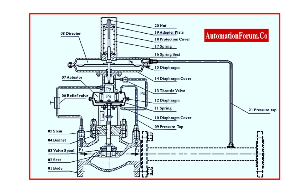
- When the control valve downstream pressure drops below the set point process fluid from the diaphragm casing retreats back to the process line.
- The pressure on the diaphragm is released and the valve is opened to flow the process fluid.
- Hence, this increased flow tends to rise the pressure back to its actual set point
- In the case of the back-pressure regulator valve, the Pitot tube connects the diaphragm casing at the upstream side of the pressure control valve
- The process fluid at the inlet side acts on the diaphragm to open the valve for high pressure or close the valve in case of low pressure respectively.
Describe the types of Self-Operated Control Valves
Types of Self Operated Control valves
1. Pressure Reducing Valves:
- These valves minimize high and frequently fluctuating pressure to an adjustable constant pressure at the outlet side of the control valve.
- The spring allows for a valve to open and gets closed when pressure rises.
2. Back Pressure Valves:
- These are known as back pressure regulators, overflow valves, or pressure-sustaining valves.
- These valves adjust constant pressure at the inlet side of the valve.
- A spring allows for the valve to close, and the valve opens with the rise in inlet pressure.
3. Bleeding and Venting Valves
- These bleeding and venting valves take out or take in air or gases automatically from tanks or to tanks, vessels, or pipelines.
- These valves are float-controlled valves, the valve gets closed as the liquid level rises and gets opened as the liquid level drops within the limit.
- Operation of these valves is independent of external pneumatic or electrical inputs.
4. Condensate & Steam Traps
- These are known as steam traps are float-controlled valves.
- These are responsible for automatically draining condensate without loss of steam or gas.
- They operate immediately inside systems
- These are not affected by backpressure or pressure fluctuations.
5. Vacuum Breakers
- Vacuum breakers safeguard the vessels, tanks, and pipelines against vacuum.
- A vacuum or negative pressure gets built up upon draining a system, or when a pump fails.
- Vacuum breakers are responsible for protection from implosion.
How to Size a Self-Actuated Pressure Regulator?
- These operating parameters shown below are required to determine actual KVS or CVS for either a pressure-reducing valve or a pressure-sustaining valve (back pressure regulator).
- It is essential to select a correct KVS factor for a pressure regulator to ensure for desired flow rate.
- Sizing and selecting a correct self-actuated pressure control valve requires the following operating parameters needs to be considered
- Inlet Pressure or Upstream Pressure (P1): Usually considered in the bar or in PSI Scale. (1 bar = 14.7 PSI)
- Outlet/Control Pressure or Downstream Pressure (P2): Usually considered in the bar or in PSI Scale.
- Flow Rate Q: Usually considered in Nm³/h or SCFM.
- Media Temperature: Usually considered in Degrees Celsius or Fahrenheit.
- Process Media: To determine its Specific Gravity, Viscosity, Molecular Weight, or Density.
Some other important factors to be considered when selecting self-acting regulators
- Materials:
- Self acting control valves are made from deep-drawn 316L Stainless Steel to provide excellent surface quality for end users.
- Before selecting a suitable material for construction we need to consider both the flowing media and installation environment.
- If the unit is installed in demanding environments or with aggressive media, higher grade alloys materials such as Super Duplex (1.4410/1.4501), Duplex (1.4462), or Titanium (3.7025/3.7035) are worth to ensure a long operational lifespan of the control valve.
- Connections:
- Standard self-acting regulators range from sizes 1/2” up to 6” or Nominal Diameter of DN15 to DN150 with a wide range of connection options including threaded, flanged, weld, and other special connections.
Typical Installations for Self-Acting Pressure Reducers
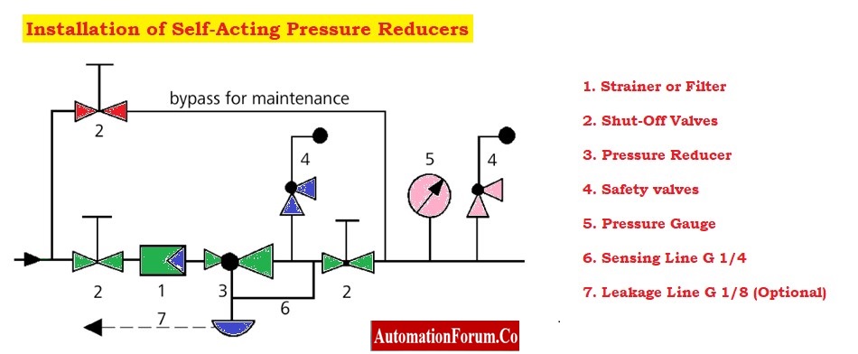
- Strainer or Filter: It is installed at the upstream side of pressure reducing valve to filter and remove dirt present in the line before the media passes through the valve.
- Shut-Off Valve: These valves are called isolation valves usually ball valves are used, and these valves are installed to isolate the flow by manual operation.
- Pressure Regulator: These are controlling devices that regulate and reduce the instrument air pressure as required for the existing process systems.
- Safety Relief Valves: These Safety relief valves are installed downstream of the pressure regulator in the unexpected event of complete valve failure (failing open). A safety valve is being pre-set to divert the pressure and flow away from any protected equipment further downstream.
- Pressure Gauge: This is only a pressure-indicating analog device installed over the control system to visualize existing pressure.
- Sensing lines and leakage line: Consideration of Sensing lines and leakage line connections are based upon selected valves and application requirements.
Application of Self-Actuated Valve
- Food & Beverage and Pharmaceutical
- Chemical & Petrochemical
- Oil and Gas
- Defense and in the Marine
- Renewable Energy & Alternative Fuels
Advantages of Self-Actuated Valves
- These valves do not require any external pressure or extra energy for actuator movement.
- These are simple type pressure control valves.
- Low cost
- Simple structure
- Reliable action
- It is suitable for small change flow rates.
Dis-Advantages of Self-Actuated Valves
- These are not suitable for continuous proportional control action.
- Instrument air/power supply is difficult
- Low adjustment accuracy
Trouble shooting problems and its potential causes
Problem-1: The pressure in the downstream direction increase above the adjusted set point
Potential Causes-1:
- Insufficient pressure pulses on the operating diaphragm.
- Foreign particles blocking the plug.
- Seat and plug are worn or leak.
- Control line blocked.
- Pressure tapped at the wrong place.
- Regulator CV coefficient too large.
- Incorrect positioning of the compensation chamber or insufficient size.
Problem-2: Downstream pressure hunts
Potential Causes-2:
- Regulator CV coefficient too large.
- The improper location was used to take the pressure tapping.
- The pressure tapping limitation in the control line is either too big or not present.
Problem-3: Slow control response
Potential Causes-3:
- There is a restriction in the screw joint of the actuator that is either too dusty or too tiny.
- Dirt in the control line
Problem-4: The pressure in the downstream direction fall below the adjusted set point
Potential Causes-4:
- Regulator installed against the flow.
- Regulator CV coefficient too small.
- The improper location was used to take the pressure tapping. (regulator having the external control line).
- Foreign particles blocking the plug
- Incorrect positioning of the compensation chamber or its insufficient size in steam applications.
- Control line blocked.
- Strainer blocked.
Problem-5: Jerky control response
Potential Causes-5: Increased friction, for example as a result of foreign particles being trapped between the seat and the plug
- Loud noises:
- High flow velocity, cavitation
- Leakage at the actuator:
- Defective operating diaphragm/bellows
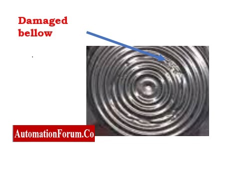
Problem-6: Leakage at the bellows seal
Potential Causes-6:
- Defective bellows seal
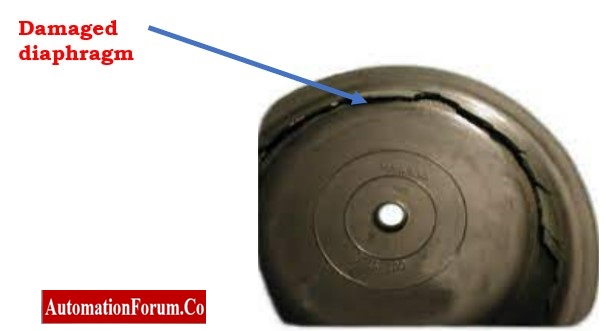
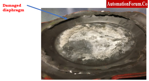
Problem-7: Color mark appears at the diaphragm rupture indicator (actuator with two diaphragms)
Potential Causes-7:
- Defective operating diaphragm.