Introduction to Conductivity Measurement
The term Conductance refers to the readiness of materials to carry an electric current. Liquids which carry an electric current are generally referred to as electrolytic conductors. The flow of current through electrolytic conductors is accomplished by the movement of electric charges (positive and negative ions) when the liquid is under the influence of an electrical field. The conductance of a liquid can be defined by its electrical properties – the ratio of current to voltage between any two points within the liquid. As the two points move closer together or further apart, this value changes. To have useful meaning for analytical purposes, a dimension needs to be given to the measurement; i.e., the physical parameters of the measurement.
By defining the physical parameters of the measurement, a standard measure is created. This standard measure is referred to as specific conductance or conductivity.
It is defined as the reciprocal of the resistance in ohms, measured between the opposing faces of 1 cm cube of liquid at a specific temperature.
The units used to define conductance are:
1/ohm = 1 mho = 1000 mS = 1,000,000 uS.
S.I. units may be used in place of mhos;
1 mho = 1 Siemen (S).
Conductivity units are expressed as
µS/cm (1.0 dS/m = 1. 0 µS/cm) or mS/cm.
What is Conductivity ?

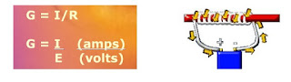
Conductivity is the ability of a material to conduct electric current. The principle by which instruments measure conductivity is simple – two plates are placed in the sample, a potential is applied across the plates (normally a sine wave voltage), and the current is measured. Conductivity (G), the inverse of resistivity (R) is determined from the voltage and current values according to Ohm’s law.
G = I/R = I (amps) / E (volts)
Principle of Measurement :

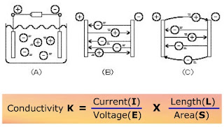
An electrolyte solution contains positive ions, each of which has a positive electrical charge, and negative ions, each of which have has a negative electrical charge. As illustrated in Fig. (A), a pair of metal plates placed at opposites sides in an electrolyte solution, and a battery is connected. The positive ions move toward the plate connected to the negative terminal of the battery, and the negative ions move toward the plate connected to the positive terminal of the battery, and thus electric current flows through the solution. When a voltage is applied, the ions move straight toward the respective oppositely charged metal plates, as illustrated in Fig. (B). Since conductivity is inversely proportional to resistance, the conductivity can be known if the resistance is measured as per the Ohm’s law.
The voltage (E) of the battery being constant, the conductivity (k) and the current (I) are proportional; therefore, the conductivity can be obtained if the current is measured.
Therefore
Conductivity K = 1 / Resistance(R) * Length(L) / Area(S)
As per the ohm’s law Resistance(R) = Voltage(E) / Current(I)
Substituting for R
We get
Conductivity K = Current(I) / Voltage(E) * Length(L) / Area(S)
Conductivity Measurement :
Conductivity measures the ability of a solution to conduct an electric current between two electrodes. In solution, the current flows by ion transport. Therefore, with an increasing amount of ions present in the liquid, the liquid will have a higher conductivity. If the number of ions in the liquid is very small, the solution will be “resistive” to current flow. AC current is used to prevent complete ion migration to the two electrodes.
The charge on ions in solution facilities the conductance of electrical current, the conductivity of a solution is proportional to its ion concentration. In some situations, however, conductivity may not correlate directly to concentration. The graphs above illustrate the relationship between conductivity and ion concentration for two common solutions. Notice that the graph is linear for sodium chloride solution, but not for highly concentrated sulfuric acid. Ionic interactions can alter the linear relationship between conductivity and concentration in some highly concentrated solutions.
Conductivity Cell:
A conductivity measuring cell is formed by two 1-cm square surfaces spaced 1-cm apart. Cells of different physical configuration are characterized by their cell constant, K. The flow of current through conductors is accomplished by the movement of electric charges (positive and negative ions) when the liquid is under the influence of an electrical field.
This cell constant (K) is a function of the electrode areas, the distance between the electrodes and the electrical field pattern between the electrodes.
Often, for considerations having to do with sample volume or space, a cell’s physical configuration is designed differently. Cells with constants of 1.0 cm-1 or greater normally have small, widely spaced electrodes. Cells with constants of K = 0. 1 or less normally have large closely spaced electrodes. Since K (cell constant) is a “factor”which reflects a particular cell’s physical configuration, it must be multiplied by the observed conductance to obtain the actual conductivity reading.
For example, for an observed conductance reading of 200 µS using a cell with K = 0. 1, the conductivity value is 200 x 0. 1 = 20 µS/cm.
The cell constant is defined as the ratio of the distance between the electrodes, d, to the electrode area, A. This however neglects the existence of a fringe-field effect, which affects the electrode area by the amount AR. Therefore K = d/(A + AR). Because it is normally impossible to measure the fringe-field effect and the amount of AR to calculate the cell constant, K, the actual K of a specific cell is determined by a comparison measurement of a standard solution of known electrolytic conductivity.
The most commonly used standard solution for calibration is 0.01 M KCl. This solution has a conductivity of 1412 µS/cm at 25oC
The Effect of Temperature
The conductivity of a solution with a specific electrolyte concentration will change with a change in temperature. The temperature compensated conductivity of a solution is the conductivity which that solution exhibits at the reference temperature. This temperature is chosen to be either 25oC or 20oC. A measurement made at reference temperature, therefore, needs no compensation. Generally for most aqueous samples, a coefficient of 2.1 % per degree Celcius is used in temperature compensation, with the apparent value being 2.1 % high for each degree C above 25oC or conversely the apparent value being 2.1 % low for each temperature for measurement is 25oC. A useful algorithm for temperature correction is:
CT = C25 [1 + 0.021 (T – 25)]
Where CT = the measured conductivity of a solution at sample temperature; C25 = the conductivity of the solution at 25oC and T = the sample temperature(oC).
Many conductivity meters today automatically compensates for temperature if the conductivity probe includes a Thermistor. However, as will be explained later, this can be a major source of error in analysis if the Thermistor is not accurate or if the instrument is improperly calibrated.
Note the two following examples to explain the effect and compensation of the fringe-field effect and temperature.