- What is a valve?
- What are the major functions of the valve?
- What are the major parts of the valve?
- Functions of Valves in Piping Systems
- How to select a valve?
- What are the different types of valves?
- What are the major types of valves?
- Isolation valve
- Regulating valve
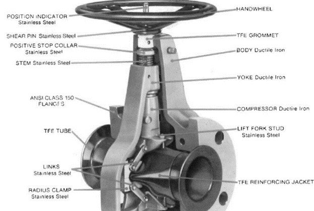
- Gate valve
- Ball valve
- Plug valve
- Globe valve
- Needle valve
- Pinch valve
- Diaphragm valve
- Butterfly valve
- Check Valve (Non-return Valve)
- Comparison between manual valves
- Classification of Valves in Piping Systems
What is a valve?
We can control the liquid flow or gas flow in an industrial process with the help of a valve. It would do this by different methods such as closing, opening, or blocking various passages in a pipe system. So this device can control the flow and pressure in a system, these valves are utilized in an industrial piping system that conveys liquids, gases, slurries, vapors, etc. In many industries, valves are used to control the flow, pressure, and also direction of the fluid. A valve is capable to open, close, or regulate the fluid flow in a process, these valves consist of a moving part that would open, close, or obstruct partially one or more passageways.
What are the major functions of the valve?
- Valves would control the process or isolate the part of the pipeline by opening and closing.
- It would allow more or less fluid to flow by varying the flow rate
- It would redirect the flow from one line to the other in a pipeline
- It would provide unidirectional flow
- Fluid pressure reduction
- It would keep the pressure in a pipeline or in a tank below a fixed maximum
- It would prevent accidents in an industrial process by relieving the overpressure in a container or in a pipeline.
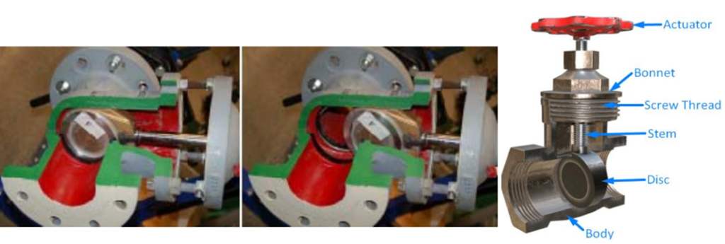
What are the major parts of the valve?
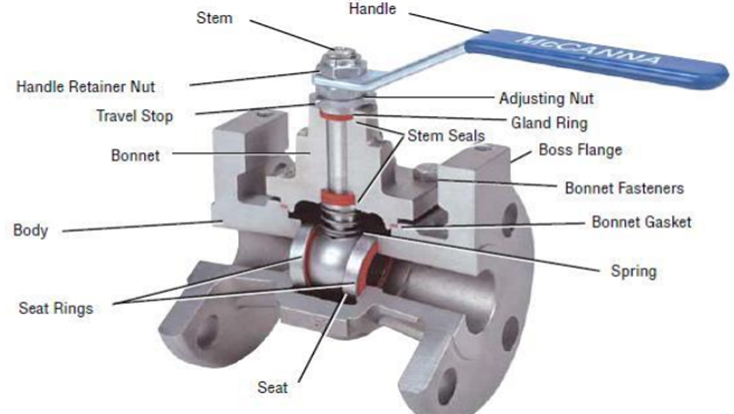
Valve body
This can be considered as the outer casing of the valve and the valve body consists of internal trim. This is the part of the valve where the fluid passes and it should be able to handle the flow pressure.
Valve bonnet
This part would act as a valve body cover, this part is bolted into the valve body. It would mostly cover the hole in the valve body, this would hold everything together inside the body
Valve trim
Trim is the name given for the replaceable parts of the valve-like disk, stem, Seat, and also the sleeves which are used to guide the stem.
- Disk – It is also known as valve member usually it is a movable obstruction inside the body that would restrict the flow through the valve
- Seat – it is also known as seal rings is the interior surface of the body and it would contact the disc to form a leak-tight seal.
Valve stem
A valve stem would transfer the input which is given to the handle to the disc, the input would be a handle motion.
Actuator
This part would operate the stem and the disk, the actuator could be manually operated or motor operated.
Packing
The major purpose of this part is to prevent leakage between the bonnet and the stem. This would act as a protection between the internal part of the valve and the outside.
Functions of Valves in Piping Systems
Valves are essential components in piping systems, enhancing efficiency, quality control, and safety. The primary purpose of valve selection is to fulfill specific functions within the system. Key roles of valves include
- Starting or stopping fluid flow
- Throttling flow rates to desired levels
- Regulating and maintaining pressure
- Controlling fluid temperature as needed
- Redirecting fluid between different pathways
- Restricting flow to balance the system or prevent over-pressurization
- Preventing backflow and ensuring proper flow direction
- Stopping flow in case of system failure
- Enhancing safety by relieving excess pressure or vacuum
During the design phase of a piping system, engineers use Process and Instrumentation Diagrams (P&IDs) to specify suitable valve types based on system requirements. P&IDs provide a schematic representation of how piping, instrumentation, and system components interact, guiding the selection of valves for specific applications
How to select a valve?
- It must be selected according to the flow direction and characteristics
- Valve size and trim size must be considered
- It should be selected according to the leakage class
- Construction material
- Packing and bonnet type
- Operating temperature
- Actuator type
- Rangeability
- It must be selected by considering the fluid properties
- End connection type must be considered like flanged, screwed, etc.
- Capacity – Cv value should be considered
- Single seated, double-seated, sliding stem type, etc.
- Plug type must be considered like V ported, contour, etc.
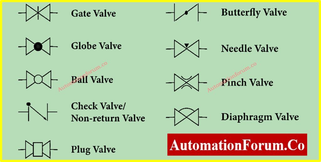
What are the different types of valves?
The table below provides a summary of various types of valves along with their corresponding P&ID symbols. Among these, the most commonly used valves include gate valves, globe valves, check valves, and ball valves, which serve essential functions in piping systems.
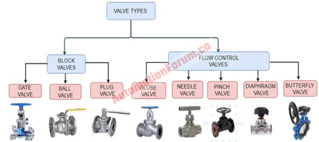
What are the major types of valves?
Isolation valve
The isolating valve can be used in a process system to stop the process media to a given location, it is mostly used for safety purposes.
Regulating valve
This type of valve is used to control the flow of the fluid by varying the size of the flow passage. This would be useful to control the process quantities such as pressure, temperature, and liquid level.
Gate valve
Gate valves can be used for underground installations, these valves can be fully opened or fully closed. It would prevent the fluid hammer due to its slow operation process. These valves are used in pipelines as isolating valves. These valves are used when a minimum pressure loss and also when the free bore is required.
Advantages of gate valve
- Good shutoff characteristics
- Bidirectional
- Minimal pressure loss
Disadvantages of gate valve
- These valves won’t open or close quickly
- Large space is required for its installation
- Maintenance of the valve seats would be difficult
Applications of gate valve
- It can be used for high temperature and high-pressure applications
- It is also used for ON-OFF applications
Ball valve
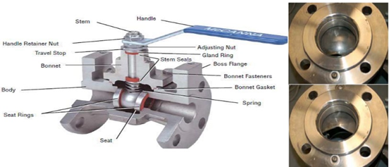
This valve uses a hollow ball to control the flow these valves are quarter-turn valves. These valves would be open when the ball’s hole is in line with the flow.
Advantages of the ball valve
- It can be easily operated
- It can be used for high pressure and high-temperature applications
- Durable and reliable
Disadvantages of the ball valve
- It can’t be used with slurries because it could be jammed due to the suspended particles
- In a closed position these valves trap water in the center cavity, this could lead to crack while ice forming
Applications of ball valve
- It can be used with corrosive fluids and slurries
- Flow and pressure control of liquids and gases
Plug valve
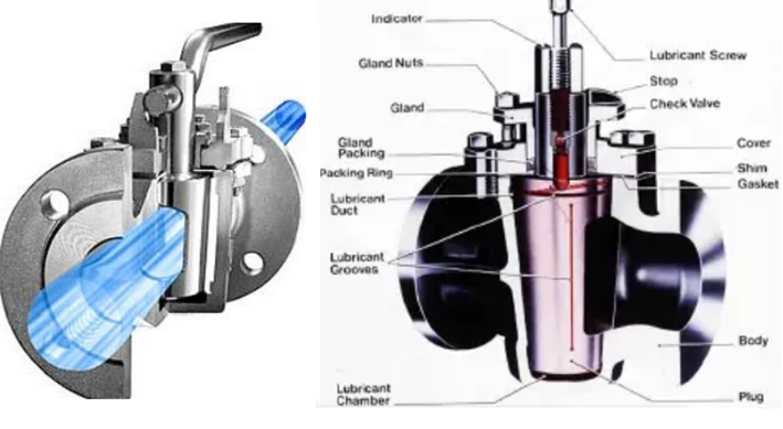
These valves would have cylindrical or conical tapered plugs and this can be rotated to control the flow through the valve. These valves are mostly used to do the full flow service where quick shutoff is needed. These valves are used for steam, water, oil, gas, and chemical liquid services.
Advantages of plug valves
- Easy to open and close
- Minimal resistance to flow
- It can be serviced in place
Disadvantages of plug valve
- Great force would be required to actuate because of high friction
- Reduced port because of the tapered plug
Applications plug valve
- Air, gaseous, and vapor services
- Oil piping systems
- Coal, slurries, mud, and sewage applications
Globe valve
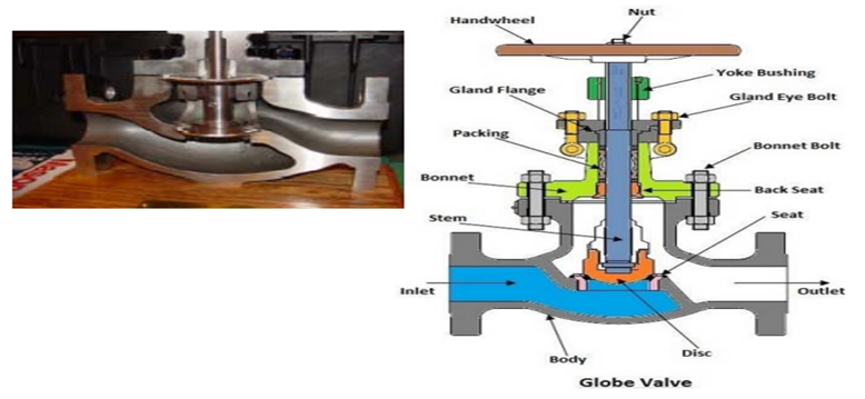
These valves are used to regulate the flow in a pipeline, it is composed of a movable disc and a stationary ring seat. These valves are used to start, stop, and regulate the fluid flow by opening and closing the passage of flow. These are linear motion valves, and it consists of a disc, valve stem, and handwheel.
Advantages of globe valve
- Throttling feature
- Fast opening and closing time
- It can be used for regular operations
Disadvantages of globe valve
- Higher pressure loss
- It would need a huge amount of force or an actuator with larger torque to close under high pressure
Applications of globe valve
- It can be used for throttling purposes
- High-temperature applications
Needle valve
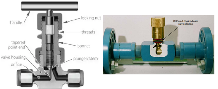
These valves are volume control valves that are used to restrict the flow in small lines. These valves are used to provide the flow to delicate gauges where fluid pressure must be controlled.
Advantages of needle valve
- Automatic combustion control system
- It can be used for precise flow regulation
- It can be used when the flow must be gradually halted
- It can be used as on/off valves
Disadvantages of needle valve
- Due to the small orifice, needle valves can cause a significant pressure drop across the valve, making them less suitable for high-flow applications.
- While they offer precise flow control, needle valves are not ideal for handling large volumes of fluid or gas due to their restricted flow capacity.
- Frequent adjustments or use with abrasive media can wear out the needle and seat, leading to potential leakage and reduced performance.
- Most needle valves require manual adjustment, which can be time-consuming and less efficient for automated systems.
Applications of needle valve
- It can only be used with clean fluids
- It has high-pressure drop when it is open
- These valves are suitable for low flow rates
- It can be used where accurate flow is required
- It is used with pressure pump governors
- These valves are also used for throttling and on/off services
Pinch valve
These valves are suitable for on/off and also for throttling services, these valves are suitable for slurries and also for liquids that have suspended solid. These valves can be used with corrosive fluids because the operating mechanism is isolated from the process fluid. These valves are composed of a sleeve that is molded of rubber and a pinching mechanism.
Advantages of pinch valve
- Straight flow passage
- Process fluid won’t be in contact with the internal moving parts
- Low maintenance
- These valves can be used with contaminated fluids
Disadvantages of pinch valve
- It can’t be used for high temperature and high-pressure applications
- It is not suitable for gas media
Applications of pinch valve
- It can be used with slurries
- It can be used with liquids that have a huge amount of suspended solids
- It can be used with corrosive fluids
Diaphragm valve
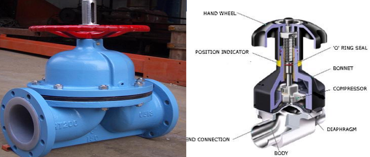
In this valve, the closing component of the valve is a diaphragm instead of a disc. This diaphragm would separate the valve trim from the process fluids that flow through the valve and due to this there is no need for stem gland packing. So when the actuator has turned the diaphragm which is attached to the stem would go down and close the valve.
Advantages of the diaphragm valve
- The major advantage of the diaphragm valve is that the components of the valve can be isolated from the process fluid
- It is constructed in a way that there won’t be any leakage
Disadvantages of the diaphragm valve
- Frequent maintenance would be required
- These valves are not suitable for high-temperature applications
Applications of the diaphragm valve
- It can be used with normal liquids, dirty liquids, and also with gases
- Pharmaceutical and food processing
- These valves are suitable for corrosive applications
Butterfly valve
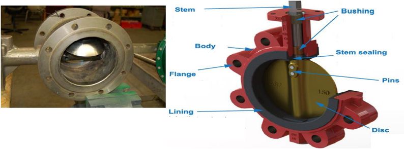
As shown in the above image the disc would be rotated while turning the actuator. So the disc would be parallel, or perpendicular to the flow, during the flow the disc would be present and this would create pressure drop even it’s in the open position.
Advantages of a butterfly valve
- It would open and close quickly
- These valves are very precise and due to this they can be used in many industrial applications
- Reliable
- Less maintenance.
Disadvantages of a butterfly valve
- Some portion of the valve would be present in between the flow
Applications of a butterfly valve
- Slurries
- It can be used for high temperature and high-pressure services
- Vacuum service
- Chemical and pharmaceutical services
Check Valve (Non-return Valve)
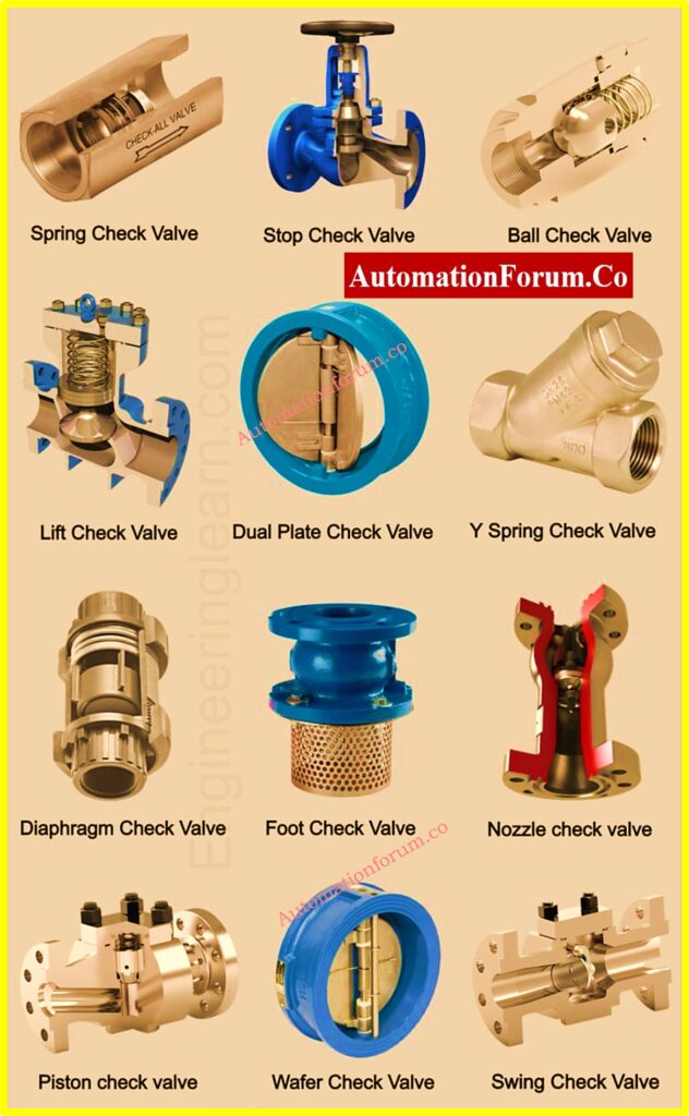
A check valve is a device that prevents backflow in piping systems. It allows fluid to flow in one direction, automatically closing when reverse flow occurs to stop fluid from moving backward. The valve operates without external control, making it simple and efficient. Typically, check valves do not have an operating handle or stem and are designed with a one-way flap mechanism for straightforward operation.
Advantages of Check Valves
- Prevents reverse flow, protecting equipment and processes.
- Operates automatically without the need for manual intervention or external control.
- Simple and compact design ensures ease of installation and low maintenance.
- Suitable for a wide range of applications due to various available types (swing, ball, piston, etc.).
Disadvantages of Check Valves
- Potential for wear and tear in the flap or mechanism due to frequent operation.
- Limited ability to handle high-pressure drops, leading to inefficiency in specific conditions.
- Backpressure or debris in the pipeline may cause the valve to malfunction.
- Not suitable for applications requiring precise flow control or throttling.
Applications of Check Valves
- Feed water control systems in boilers.
- Gas systems that combine multiple gases into a single stream.
- Fuel and oxidizer mixing systems in aerospace or industrial processes.
- Preventing the mixing of potable water with contaminated water systems.
- Ensuring unidirectional flow in household heating systems or irrigation setups.
- Protection of pumps and compressors by avoiding reverse flow.
- Hydraulic systems to maintain pressure and prevent backflow.
Comparison between manual valves
| VALVE TYPE | DUTY | SERVICE |
| Globe | Controlling, starting, and stopping the flow | Gases, liquids, cryogenics |
| Gate | Frequent valve operation Starting, stopping, and controlling the flow | Gases, fluids with solids, vacuum, slurries, and contaminated fluid |
| Ball | Throttling, flow diversion, starting and stopping | Gas, liquid, vacuum, cryogenics, corrosive and non-abrasive slurry |
| Plug | Throttling, flow diversion, starting and stopping | Gas, liquid, vacuum, sticky fluids, corrosive fluids, and granules |
| Butterfly | Start, stop and flow control | Gas, liquid, vacuum, slurries, powder, granules, and foodstuff |
| Pinch | Start, stop and flow control | Liquid, vacuum, slurries, powder, granules, and corrosive |
| Diaphragm | Start, stop and flow control | Gas, liquids that carry solids, viscous fluid, vacuum, slurry, sludge, and hazardous fluids |
| Needle | Flow regulation | High-pressure applications |
Classification of Valves in Piping Systems
Valves can be categorized in various ways to ensure suitability for specific applications. Key classifications include function, operating mechanism, end connections, mechanical motion, construction material, and pressure-temperature ratings. Understanding these categories helps in selecting the right valve for a given process.
(A) Classification by Function
Valves are used for a variety of purposes such as starting/stopping flow, regulating pressure or flow, controlling flow direction, or ensuring process safety.
They are broadly categorized as isolation valves or regulation valves:
Isolation Valves:
Designed to either fully stop or allow unrestricted fluid flow. These valves are not ideal for continuous partial operation, as it may cause wear or poor performance.
Examples: Gate valve, ball valve, plug valve.
Regulation Valves:
Used for precise control of flow and pressure. These valves can be safely used in partially open or closed states.
Examples: Globe valve, needle valve, diaphragm valve.
Some valves perform both isolation and regulation functions depending on design and application.
(B) Mode of Operation
Valves are also categorized based on how they are operated:
Manual Valves:
Operated by hand using levers, wheels, or knobs. Mechanisms like gears may be added for speed or torque adjustment.
Actuated Valves:
Integrated with systems for remote or automated control using:
- Electric Motors: Use reversible motors and gears for controlled operation.
- Pneumatic Systems: Utilize air pressure to actuate the valve.
- Hydraulic Systems: Employ pressurized liquids and pistons for movement.
- Solenoid Systems: Use electromagnetic force to operate the valve.
Automatic Valves:
Activated by specific flow or pressure conditions. For example:
- Check valves close automatically during reverse flow.
- Pressure relief valves open during overpressure conditions.
(C) End Connections
Valves connect to pipes through various joints, ensuring proper integration into the system. Common types include:
- Flanged Ends: Two flanges are bolted together to form a joint.
- Screwed Ends: Threaded joints for quick assembly.
- Socket Welded Ends: Pipes are inserted into a socket and welded.
- Butt Weld Ends: Beveled ends are welded for a secure connection.
- Wafer Type: Compact valves placed between pipe flanges, ideal for limited spaces.
(D) Mechanical Motion
Valves can be classified by the movement of their closing elements:
- Linear Motion Valves: The closing element moves in a straight line to open or close.
Examples: Gate valve, globe valve, pinch valve. - Rotary Motion Valves: The closing element rotates to control flow.
Examples: Ball valve, butterfly valve, plug valve. - Quarter-Turn Valves: Require only 90° rotation for full operation.
Examples: Ball valve, butterfly valve.
(E) Construction Material
Valve bodies are made from materials such as stainless steel, brass, cast iron, or plastics, chosen for durability and compatibility with the application’s pressure and temperature requirements. Seals and gaskets are typically made from PTFE, FKM, or EPDM to ensure proper sealing and withstand operating conditions.
(F) Pressure-Temperature Ratings
Valves are also classified based on their maximum pressure and temperature thresholds, which indicate the safe operating limits for the valve in the given system.
These classifications serve as a guide for selecting valves tailored to specific processes, ensuring operational efficiency and safety.