PLCs are major control systems used in various industrial applications. We can see PLCs in almost all of the industrial processes. The major functions of PLCs are sensing signals from field devices, sends commands to field devices as per the control logic, timing, counting, PID control, etc. A PLC is composed of logical components so according to input logical value the output will be produced and this would vary the status of the system.
How should we select a PLC for our industrial applications?
Below mentioned are the major factors to be considered while selecting a PLC
• CPU type
• Input power supply
• DC voltage used
• Operation modes
• Status indicators
• Number of Digital Input & Output
• Number of Analogue Input & Output
• I/O voltage
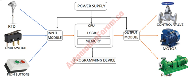
Hardware components of PLC

A module is a PCB that is placed in an enclosure, PLC modules are situated inside the chassis. So the power must be cut off while inserting or removing a module. The modules should be handled properly otherwise there could be circuit damage. A PLC module can be seen in the slots, slots are placed near to the backplane, slots are located in the chassis. The backplane is a chassis part and it is a big PCB that consists of the address bus, system data bus, power bus, and connectors.
Major PLC modules are
- Power Supply Module
- Input Module
- Central Processor Unit (CPU)
- Output Module
- PLC Chassis
- PLC rack
- Relays
- Communication modules
- Field termination assembly
1. Power supply module
This is an integral PLC part and it would provide power to the input and output modules and also to the processor. In this section, the AC voltage will be converted to DC voltage.
2. Input module
This module is required to interact between the input field device and the controller. The input devices would be hardwired to the input modules, the input modules are required to sense and send signals to Control Processor Unit (CPU). Input devices would provide the status information and this will be done by devices such as push buttons and sensors. These devices would be connected to the input modules. These input modules would provide the field signals from the input devices at a low voltage level which will be suitable for CPU processing.
Analog and Digital input can be processed by the input module, mostly Digital inputs are used for industrial processes. The input interface would receive the signals from the machine and this would be converted into a suitable signal which can be used by the CPU. So basically, an input interface would provide the status information regarding the process which is to be controlled by the PLC.
Types of the Input module
Analog Input module
This is used to convert the analog signals received from certain devices such as pressure sensors. The Pressure sensor would provide an analog signal and this signal can be converted to digital with the help of an analog to digital converter (A/D Convertor or A to D Convertor) circuit in the Analog Input module.
Digital input module
This input module would convert the digital input signal to a lower voltage digital signal and this signal will be processed by the CPU as per the control logic and a corresponding response will be generated.
3. Central processing unit (CPU)
This is the major part of the PLC and this part is really important to do the industrial process control. The CPU would do various logical and data manipulation functions and this would be done with the input/output sections. This device would help the PLC to communicate with the computer, field devices, and it can also communicate to other PLCs.
In the fixed PLC the CPU will be inbuilt, while in the modular type a plug-in module is used. The processing module has two parts, one is the CPU section and the other one is the memory section. The program execution will be carried out by the CPU while the memory section would store the program. The required power for the processor would be provided by the PLC power supply. In a PLC CPU, we can find a microprocessor and this microprocessor is designed for industrial control applications. Certain PLCs would contain two processors such as a fault-tolerant PLC.
Major functions of a PLC CPU
- Accepts status information from different input devices
- Execution of the program
- Proper steps will be taken to the machine operation or the process
- It does many logic functions
- Provides the required output signal to control the output field devices such as control valves, relay coils, etc.
What are the different operating modes of PLC CPU?
- Run
- Program
- Remote
Run mode
In this mode, the program will be executed and also it would energize the output devices. In this mode, there won’t be any online program editing. We can’t change the processor mode by using the programmer/operator interface in this model.
Program mode
In this mode, the processor will be prevented from scanning or executing the program and the output of the controller won’t be energized. Editing and program entry are possible in this mode. In this mode, we can’t change the processor mode by using the programmer/ operator interface.
Remote mode
We could change the processor mode by using this with the help of the programmer/operator interface. We could choose the remote mode such as Remote Run, Remote program, or Remote test mode.
4. Output Modules
The output field device and the controller interaction would take place because of this module. The output devices could be a valve, motor, pump, lamps, etc. The signal from the CPU to control the field devices would be low-level signals and these signals would be amplified by the output module.
What are the functions of I/O modules?
- Processor communication to the field device is facilitated
- Connection of the field device to PLC
- Facilitate the connection for the machine and process
- It would vary input/output signal strength according to the requirement
- Provides discrete signals to the PLC from the input device and transmits the ON/OFF signals from the PLC to the output device.
5. PLC chassis
We can define chassis as the enclosure of the modular PLC. Basically, it is a hardware assembly that integrates components such as a power supply, a processor module, and also I/O modules.
How chassis is divided into I/O groups
One slot addressing
This type of slot addressing is used in case if one chassis slot is used for one I/O group
Two slots addressing
When one I/O group is spread across two chassis slots, then this type of addressing is used.
Half slot addressing
If two I/O groups are in one chassis slot, then this type of address is used
6. PLC rack
Synchronization of the power and signal communication can be done in a PLC with the help of a rack. The rack is composed of many input and output modules, a logical rack is composed of 128 I/O points. The rack would use an 8-word input image table and also an 8-word output image table. I/O group can be defined as a word that is in the output image table file and also the corresponding word in the input image table file. So with the help of the rack, we can easily locate the I/O modules near to the field devices and because of this, less wiring is required. The remote rack would have a separate state number so that we can easily determine each rack. The local rack is linked with the remote rack with the help of communication modules. There would be only one rack for small PLCs and due to this, it has fixed I/O addressing. We can keep the I/O modules anywhere in the rack but mostly they are kept together for easy wiring.
So basically, a rack is a component that can hold everything together, the rack can be of different sizes according to the I/O modules. The cards can communicate with the CPU through the rack and also the power supply is connected to the rack and thus the modules which are connected to the rack would receive a regulated DC power.
How to assign rack numbers
- Eight I/O groups are one I/O rack number in any addressing mode
- Based on the size of the chassis and addressing mode we can assign up to 4 racks to our processor
- We can’t split the processor local resident I/O rack for more than one chassis
- We can’t assign the unused processor resident I/O groups to the remote I/O
- The default address of the processor local rack will be zero
- Racks cannot be split across remote I/O
7. Relays
The purpose of the relay is to do the control action, so with the help of this device, a control signal will be transformed into a control action. Isolation between the output modules and field devices can be achieved by this device. Huge action can be done with a small signal and the operator interaction would be reduced due to this device. The relay would also act as an insulation between the high and the low voltage of a circuit portion. The operation of the relay is carried out with the help of a magnetic field.
Major functions of the relay in PLC automation
- Assembly line controlling
- Motor starting
- Load controlling
- It could switch off a large electric current
- Overheating of the motor can be prevented
- It would detect if the current or voltage exceeds the limit
8. Communication modules
The communication modules would be useful to transfer and receive data in a PLC. An example of this will be MODBUS this type of communication protocol is designed to exchange data between electronic devices. So with the help of communication protocol, a PLC can communicate with the industrial facility, like a computer or any other device which is connected with the PLC.
The major purpose of PLC communication modules
- We can change the program from a desktop
- I/O points and memory elements can be forced, from a remote terminal
- We can link or connect a PLC into another PLC and also to a computer
- Alarms and data can be monitored
PLC serial communications
Normally PLC would do serial transmission of the data
RS232
This is used for very short communication purposes and by this, we can do communication with computer hardware and peripherals.
Local area network (LAN) or Ethernet (TCP/IP) – RJ45 cable
By using this communication there will be a link between all the devices, so devices can communicate with other machines.
RS 422/485
This is used for long-distance communication and it can be used to do the data transfer between several computers.
List of different propitiatory PLC communication protocols
| Sl No | PLC Manufacturer | Communication network |
| 1 | Allen Bradley | Data Highway |
| 2 | Modicon | MODBUS |
| 3 | General Electric | GE net factory LAN |
| 4 | Mitsubishi | MELSEC -NET |
| 5 | Schneider | SY/NET |
| 6 | Texas instruments | TIWAY |
MODBUS
It can transfer data between PLCs and computers, it works with Master-Slave architecture.
PROFIBUS
It is a communication protocol that can be used to transfer data from the input filed devices to the PLC and also carry signals from PLC to output control elements.
Ethernet/IP
This protocol can be used to connect or transfer data between different industrial devices such as PLCs, sensors, and other industrial machines.
Interbus
This type of protocol can be used to do the communication between computers and PLC, so this protocol will be useful to transfer data between control systems
9. Field termination assembly
In this section, the field signals from the field service cables will be assembled and they will be connected to the I/O cards through the system cables. The field termination assembly is mounted on the marshaling cabinet. The major purpose of this is to connect the sensors and actuators of the field to the respective I/O modules.
Different types of FTA
- High-level analog input
- Smart transmitter interface
- Low-level analog input
- 120 Vac Digital input (DI)
- 240 Vac Digital input (DI)
- 120/240 solid-state digital output (DO)
- Pulse input
- Serial device interface
- RHMUX