What is RVDT?
RVDT is a passive type transducer. RVDT means Rotary Variable Differential Transformer. It is also an electromechanical-based inductive transducer that converts angular displacement linear output. RVDT main function is used to sense the angular displacement into proportional electrical signal.
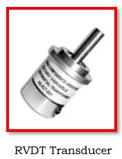
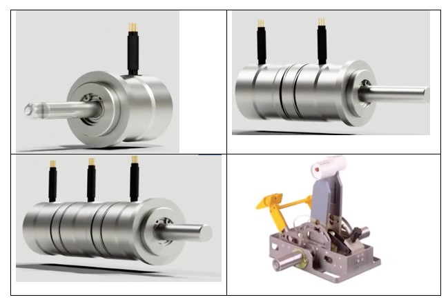
LVDT and RVDT operate in similar ways. In contrast to RVDT, which uses a cam type core for displacement measurement, LVDT uses an iron core in its construction. Using the shaft, the cam type core will rotate between the transformer’s two windings. An RVDT transducer is shown below.
What is RVDT stands for?
RVDT stands for Rotary variable differential transformer (RVDT).
RVDT Construction:
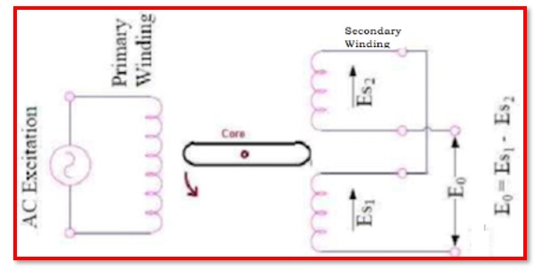
The following is RVDT construction diagram. It illustrates the two windings of an RVDT transducer, which are identical to those of a typical transformer and include a primary winding and two secondary windings. The transformer have two windings, where each secondary winding has an equal number of windings. On both sides of the transformer’s primary winding are these. A shaft and a cam, composed of soft iron, create the magnetic core of the device. As a result, this core can be turned between the windings.
Both the RVDT and LVDT are built similarly, but the primary distinction is the design of the core in the transformer windings. The transformer’s two windings will rotate around this core because of the shaft.
RVDT Working:
RVDT’s are linear across a range of 40 or -40 degrees. The input voltage range is 3V RMS at frequencies between 400 Hz and 20 kHz, and the sensitivity ranges between 2mV and 3mV per degree of rotation.
When the excitation is applied to Primary of transformer, the magnetic field is induced in secondary winding. This magnetic field cause mutual current. Therefore, an EMF is created in secondary coils (S1 and S2) which are Es1 & Es2 respectively. The output voltage is difference between the two induced secondary voltages.
The working of RVDT can be analyzed using 3 different case.
Case 1: When the Core is at Null Position.
Case 2: When the Core rotates in Clockwise Direction.
Case 3: When the Core rotates in anticlockwise Direction.
Case 1: When the Core is at Null Position:
When the shaft is placed at the null position then the induced emf in the secondary windings is identical but reverse in phase. Thus the differential output potential will be zero, and the condition will be E1=E2, where E0=E1-E2=0.
Case 2: When the Core Rotates in Clockwise direction:
In the second case, more core will enter over the primary winding as the shaft rotates in a clockwise manner. As a result, the primary winding experiences a larger induced EMF than the secondary winding. The condition will be E1>E2, where E0=E1-E2= Positive, and the differential output potential is therefore positive.
Case 3: When the Core Rotates in Anti Clockwise direction:
In this condition, when the shaft rotates in the direction of anticlockwise; more section of the core will enter across the primary winding. Therefore, the induced EMF across the secondary winding is higher than primary winding. Hence, the differential output potential is negative, and the condition will be E2>E1, Where E0=E1-E2= Negative.
Theory of RVDT:
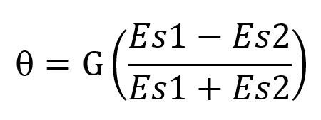
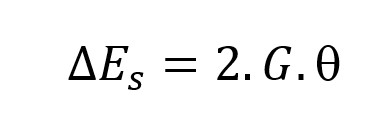
The secondary voltage is denoted by Es1 & Es2 and sensitivity of RVDT is denotes as G.
Angular displacement of the shaft will be
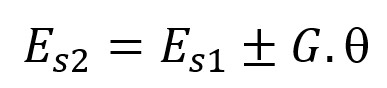
The secondary voltage is obtained by following equation
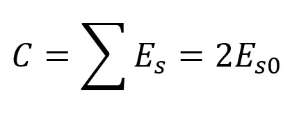
The differential output voltage E0 =Es1-Es2
The sum of total voltages is constant C.
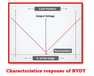
RVDT Characteristics:
RVDT characteristics response is similar to LVDT. The response is plotted between angular displacement to output voltage.
What is advantage of RVDT?
- High reliability and accuracy
- Long performance life
- Repeatability
- Small and strong construction
- Low cost
- Infinite resolution
- High linearity
- Wide variety of dimension ranges
What is disadvantage of RVDT?
- Constant contact between the measuring exterior and the nozzle is not achievable.
- The utility of the RVDT is constrained by its linear output, which ranges from +40 to -40 degrees.
RVDT Applications:
- The engine fuel management system.
- Avionics and aircraft.
- Air bleed systems for engines.
- Actuators for both engine and flying control.
- The fuel valve and hydraulics.
- Use in a cable system in brake.
- Contemporary machinery.
- Steering systems.
- Torpedo and weapon system.
Comparison between LVDT and RVDT:
| Parameter | LVDT | RVDT |
|---|---|---|
| Senses | Linear movements | Angular movements |
| Acronym | Linear Variable Differential Transformer | Rotary Variable Differential Transformer |
| Construction | Rectangular | Cam-shaped |
| Sensitivity | 2.40 mV /V/degree of rotation | 2 to 3 mV /V/degree of rotation |
| Excitation Voltage | Requires 1V to 24Vrms | Requires minimum of 3 V |
| Frequency | 50 Hz | 400 Hz to 20KHz |
| Applications | Used in measuring pressure, pressure and other products inspection | Controlling units such as fire monitoring, antenna, and radar systems |
Key difference between LVDT and RVDT:
Even though the structure of an RVDT and LVDT is easier, measuring non-linearity errors, threshold factors and maximum precision values requires a lot of work.
Magnetic shielding properties are attained using ferromagnetic materials.
Due to eddy current loss in the core, the primary voltage and secondary impedance are typically traded off in most cases. The carrier frequencies of LVDT and RVDT are roughly tuned to 2.5–5 kHz and 5–10 kHz, respectively, to address this issue.
In general, LVDT and RVDT are employed in a variety of applications where systems with minimal wear and tear properties are required. The future prospect deals with the use of LVDT and RVDT at their highest level. Various sorts of study are carried out in a similar sector to establish its advantage utilising external sources.
What is the function of RVDT?
A rotary variable differential transformer (RVDT) is an electromechanical inductive passive transducer that generates a variable AC output voltage that is directly proportional to angular displacement of input shaft.
List real time application of RVDT
- RVDT transducer has good resistance toward hostile condition for measuring rotary angle in JET.
- RVDT transducer is used on the thrust level.
- RVDT based position sensors for aerospace applications.