- What is a Load Cell and How Does it Work?
- Why Do Load Cells Fail?
- Common Symptoms of Load Cell Problems
- Step by Step Load Cell Troubleshooting Procedure
- Visual examination
- Methods of Testing
- TEST 1: Zero balance
- TEST 2: Bridge integrity
- TEST 3: Insulation resistance
- TEST 4: Shock resistance
- Downloadable template for a load cell troubleshooting checklist
- Frequently Asked Questions on Load Cell Problems
This Technical Note’s goal is to use basic instrumentation, such as a digital multimeter and a test load, to carry out a quick inspection to discover load cell troubleshooting in the field.

What is a Load Cell and How Does it Work?
A load cell is a sensor that converts force or weight into an electrical signal. It is commonly used in weighing systems, tanks, hoppers, truck scales, and industrial process applications.
Most load cells use strain gauges attached to a metal element. When a load is applied, the element deforms slightly, causing the strain gauges to change resistance. These changes are converted into a small electrical signal through a Wheatstone bridge circuit. The signal is then processed by an indicator, PLC, or control system to display the measured weight.
Why Do Load Cells Fail?
Mechanical Failures
Mechanical problems include:
- Overloading
- Shock loading
- Side loading
- Misalignment
- Excessive vibration
- Mechanical fatigue
These issues can permanently damage the sensing element and affect accuracy.
Electrical Failures
Common electrical failures include:
- Broken cables
- Loose connections
- Short circuits
- Open circuits
- EMI interference
- Power supply issues
Electrical faults often cause unstable or incorrect readings.
Environmental Factors
Environmental conditions can degrade load cell performance, including:
- Moisture ingress
- Corrosion
- Dust contamination
- Chemical exposure
- Temperature fluctuations
- High humidity
These factors can lead to drift and insulation problems.
Human Errors
Many load cell issues result from:
- Incorrect wiring
- Improper calibration
- Poor grounding
- Installation mistakes
- Lack of maintenance
Following manufacturer guidelines helps prevent these problems.
Common Symptoms of Load Cell Problems
The following table summarizes the most common load cell symptoms and their likely causes.
| Symptom | Possible Cause |
| No output signal | Broken cable, open circuit strain gauge, loss of excitation voltage, damaged load cell |
| Unstable reading | Electromagnetic interference (EMI), loose connections, vibration, moisture ingress |
| Signal drift | Temperature variation, mechanical creep, moisture contamination, strain gauge deterioration |
| Negative reading | Reversed signal wiring, incorrect calibration settings, polarity errors |
| Incorrect weight indication | Calibration error, overload damage, improper installation, wrong scaling parameters |
| Non-repeatability | Mechanical binding, structural interference, side loading, loose mounting hardware |
| Fluctuating output | Grounding issues, electrical noise, damaged cable shielding |
| Reading stuck at one value | Failed strain gauge, damaged amplifier, wiring fault |
| Slow response | Mechanical obstruction, excessive filtering in the indicator, damaged sensing element |
| Zero shift | Temperature changes, overload event, permanent deformation of the sensing element |
| Full-scale output with no load | Short circuit, severe overload damage, internal bridge failure |
| Intermittent readings | Loose terminals, broken conductors, moisture inside connectors or junction boxes |
Understanding these symptoms is the first step in developing an effective load cell troubleshooting strategy. By matching the observed behavior with likely causes, maintenance technicians can quickly narrow down the root cause and reduce troubleshooting time.
Step by Step Load Cell Troubleshooting Procedure
Visual examination
- The load cell must first be visually inspected to identify any flaws or changes in relation to a new one. Look over the following:
- Examine the load cell’s overall condition: it must be clean and free of corrosion.
- Examine the sealing: It must protect internal circuitry from moisture or other impurities. • Silicone or metallic covers must be intact, free of cuts, impacts, corrosion, or holes.
- Check the cable: It must maintain its original length and be free of damage such as cuts or twists.
- Check the cable gland near for any damage in the loadcell cables.
Methods of Testing
Load Cell Troubleshooting Flowchart
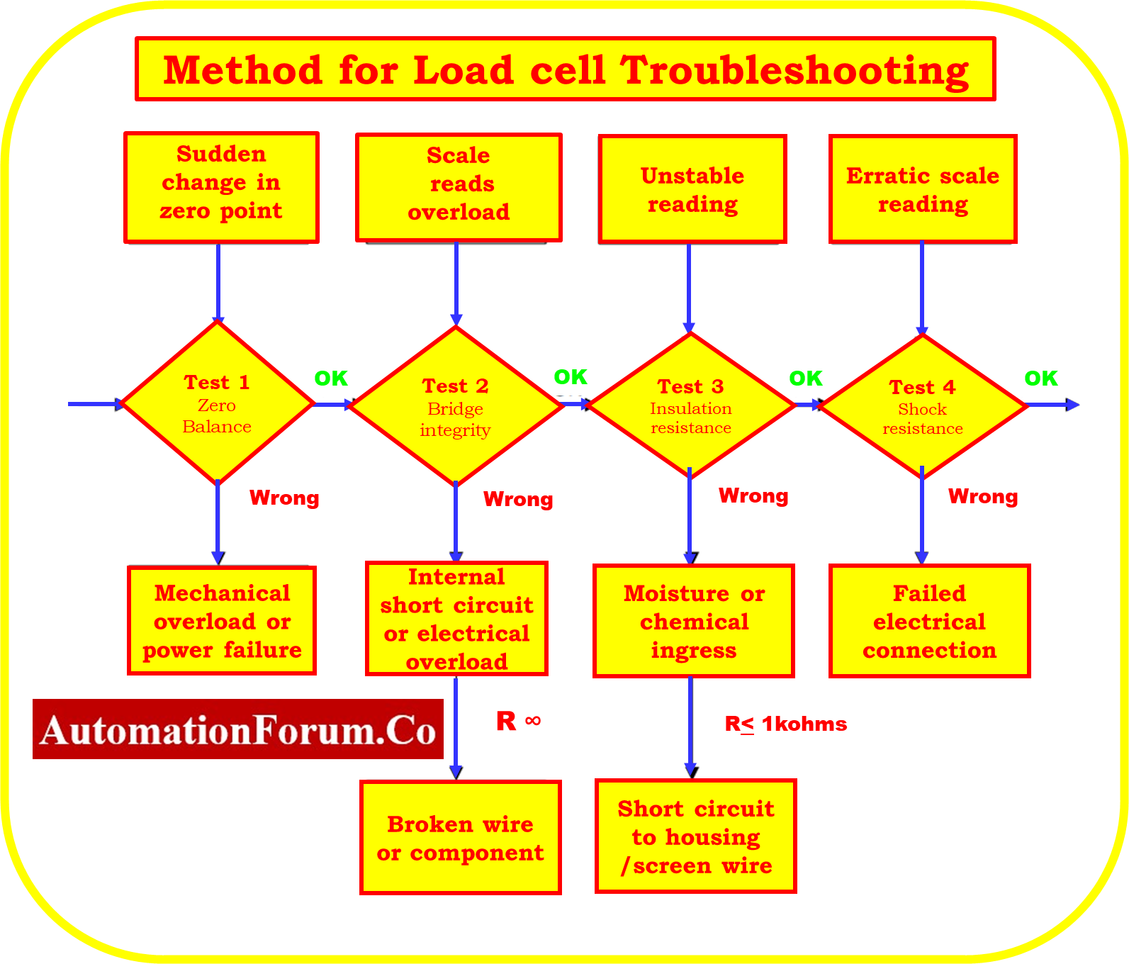
How do you test a load cell sensor?
TEST 1: Zero balance
The goal is to determine whether or not the output signals that are being supplied by the load cell are coherent. Connect the excitation wires of the load cell, which are VIN+ (green) and VIN- (black), to the power supply of the electronic indication that is being used on the scale. Disconnect the signal wires, which are VOUT+ (red) and VOUT- (white). After that, make a careful note of the following precautions:
Voltage (V) of the power supply
By monitoring the voltage between the load cell’s VIN+ (green) and VIN- (black) wires, you can confirm that the proper supply voltage is being given to the load cell.

Output signal (mV) without a load
- Read the mV output signal across output wires VOUT+ (red) and VOUT- (white) with the load cell in operating position and no dead load applied.
- The output signal needs to be consistent and within the manufacturer’s tolerances, which are +2% of 2 mV/V is equal to +0.04 mV/V (the output signal will be within +0.4 mV if the power supply is 10 v).
- The scale can typically be recalibrated when the zero shift of the load cell remains within +0.2 mV/V; if the power supply is 10V, it might be within +2 mV. The load cells can typically work with zero shifts of roughly 10%.
- For tolerance, please refer to the data sheet provided by the load cell manufacturer.

Signal output at load (mV)
As you apply a test load and read the output signal in mV across wires VOUT+ and VOUT- , place the load cell in operating position. Perform the following tests:
- The signal continues to increase correctly. Put some pressure on the signal (even manually with your hand) to observe if it moves to the predetermined sense.
- Signal constancy. Put or hang a static load and check the signal stability. The signal stability must be better than +0.002 mV (or 2 microV/V).
Analysis
- It is required to check for irregularities in the power supply and the wiring connections between the load cell and the power source if the power supply is not steady and sufficient to power the load cell.
- When a load cell is permanently damaged as a result of mechanical overloads or shocks, zero balance changes.
- Moisture, insulation failures, or modifications to bridge integrity can have an impact on load cells that face progressive zero output changes over time.
- If the output signal does not increase in the anticipated applied load sense, the wiring connections need to be checked.
How do you check a cell with a multimeter?
TEST 2: Bridge integrity
The purpose is to see if the electrical circuit inside the internal load cell retains its initial value. Any component that malfunctions often experiences a change in its electrical characteristics, which causes an increase or decrease in electrical resistance. This process involves disconnecting all of the load cell’s cables and reading the resistance and insulation values.
Resistance at the input
Read the electrical resistance in Ohms between the VIN+ (green) and VIN- (black) excitation lines. The obtained value must fall within the data sheet’s limits. Depending on the load cell model, we have varied standards, however they are often 400±30 ? or 800±30?.
Resistance at output
Read the electrical resistance in Ohms between the VOUT+ and VOUT- signal output wires. The obtained value must fall within the data sheet’s limits. Depending on the load cell model, our criteria vary, but they are typically 350 ±5? or 700 ±5?.

Analysis
The breakdown of an electrical component, a broken wire, or an internal short circuit is the most frequent causes of changes in bridge resistance. This could happen as a result of overvoltage (which could cause welding or lightning), bodily harm from stress or vibration, or high temperatures.
TEST 3: Insulation resistance
The aim is to confirm that the electrical circuit of the load cell maintains its initial values without drifting. It is required to read the insulating resistance values without connecting any wires.
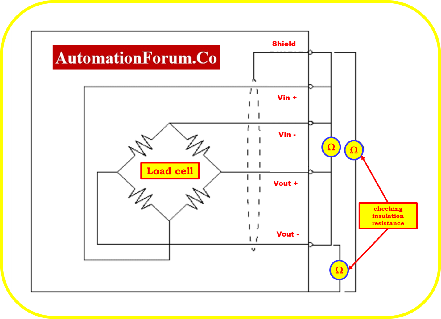
Verify the performance of the following insulating resistances:
- Insulation circuit to metal body: The resistance between a wire from a load cell (any of the “colour” wires) and the metal body of the load cell.
- Insulation circuit to shield: The resistance between the shield of the cable and any “colour” wire used in a load cell.
- Insulation between the metal body and the shield: The resistance between them. Almost all load cells are not attached to the metal body by default, however in some circumstances this can be changed.
- The outcomes must be open circuit, contact-free, and drift-free. The insulating resistance should be 500 M ohms or higher, and a mega ohmmeter should be used if possible.
- In the absence of a mega ohmmeter, it is crucial to take the same precautions with a regular ohmmeter set to the maximum scale (20 M ohms range) to identify insulating issues.
Safety Note: To prevent load cell damage, take care not to use a mega ohm meter that provides voltages more than 50 volts.
What are the symptoms of a bad load cell?
Analysis
The shield and the metal body must be isolated from the load cell’s circuit. A shield must be separated from a metal body (barring special circumstances). Insulation issues, which can result in reading instability, are typically brought on by mechanical stress on the load cell cable or wires (internal or external), water, or corrosive substances. Short circuits can result in extremely low values (< 1 k?)
TEST 4: Shock resistance
Connect the load cell directly to a power source, or better yet, a weighing indication. If your system has multiple load cells, disconnect all of them.
Apply soft impacts to the load cell with the multimeter connected between the VOUT+ (red) and VOUT- (white) wires. You can do this by using a very small hammer or screwdriver, for example.
Safety note:The load cell should not be overloaded or damaged, especially if it has a low capacity.
Analysis
Before and after the test, read the multimeter. The output readings must remain constant and return to their initial values after many impacts. Erratic readings could be a sign of an electrical transient-induced component failure or glue layer damage between the load cell body and the strain gauge.
Downloadable template for a load cell troubleshooting checklist
By clicking the link below, you can get the excel document that contains the template for the Troubleshooting Checklist for Load Cells Installed in the Industrial Weighing System.
Downloadable template for a load cell troubleshooting checklist

Frequently Asked Questions on Load Cell Problems
Why is my load cell reading unstable?
Unstable load cell readings are commonly caused by electrical noise, loose wiring connections, vibration, moisture ingress, or poor grounding. Check the installation, shielding, and wiring to identify the source of the fluctuation.
What causes load cell drift?
Load cell drift can occur due to temperature changes, moisture contamination, mechanical creep, or strain gauge deterioration. Drift typically appears as a gradual change in the displayed weight even when the load remains constant.
How do I test a load cell with a multimeter?
A load cell can be tested by measuring the input resistance, output resistance, and insulation resistance using a multimeter. Compare the measured values with the manufacturer’s specifications to determine if the load cell is functioning properly.
What is zero balance in a load cell?
Zero balance is the output signal produced by a load cell when no load is applied. An excessive zero balance value may indicate overload damage, mechanical deformation, or internal strain gauge problems.
How often should load cells be calibrated?
Calibration frequency depends on the application, usage, and accuracy requirements. Most industrial facilities perform load cell calibration annually, while critical weighing systems may require more frequent verification.
Can a damaged load cell be repaired?
Minor issues such as damaged cables, connectors, or junction boxes can often be repaired. However, load cells with damaged sensing elements, strain gauges, or permanent mechanical deformation usually require replacement.